A few weeks ago i scored 12 STE47N50 mosfets for cheap on ebay that have a really nice fat SOA, as much as 4A at 100V Vds, hence why i bought them. How often do you see a SOA like that on a mosfet ?
This is my test circuit which is open for suggestions on improvements as a simulation reveals quite horrible things at 20kHz which i just cannot get rid of no matter what i try: http://i.imgur.com/cpuuf.png
My test setup using this circuit works and sounds pretty decent though, i have bias current set to around 100mA, the source resistors are 0.47ohm 25 watt DALE resistors.
The idea is to use six of these fets per channel. What do you guys think ?
Is this on the picture the real circuit with real elements?
This MOSFET's have a huge input capacitance - 12nF and your schematic seems to have not enough current trough the driver stage to effectively drive it. Try increasing this current to more than 40mA and test again. For one pair will be good but you intend to use 6 pairs and driving this enormous capacitance will be a hard task so your driver stage will need a radical change. Your VAS current also seems to be too low I think. Try to rise it to 10mA and try to make it better with cascoding or adding a beta device.
This are my advises. They are not intended to work at 100% but you can try them and see (hear 🙂 ) the result or not.
Here is the datasheet of the MOSFET's - http://www.datasheetarchive.com/dl/Datasheets-17/DSA-331781.pdf
Have a nice day!
Last edited:
I already have the datasheet. Despite the 12nF input capacitance, it still sounded pretty good over the entire audio band, it even managed to oscillate at several hundred kHz before i changed out the resistor between output and emitter of the lower drive transistor to 91 ohms from 1.8 ohms.
In the simulation however the circuit posted is badly distorted at 20kHz with over 6% THD, lowest i can possibly get in simulation is 0.4% and that is by pushing VAS(2N5401) to its mere limit, using a stronger VAS(MJE350 or MJE15033) to cope with the increased current just brings the thing back to the horrible THD levels.
Either this circuit/topology sucks, or theres something wrong with bob cordell's spice models im using, or my version of ltspice is corrupt in some way.
OK then maybe something is wrong with your software. I'm not using LTSpice but Multisim and will simulate the schematic in the first post and see what is happening or is there any difference. Will post the result.
I also played a bit with NMOS amp not long ago and you can look it here: http://www.diyaudio.com/forums/solid-state/199336-my-new-design-updated-old-one-14.html
It is almost the same topology and soon will be put in box and will be my new amp. Sound is very good.
Regards!
I also played a bit with NMOS amp not long ago and you can look it here: http://www.diyaudio.com/forums/solid-state/199336-my-new-design-updated-old-one-14.html
It is almost the same topology and soon will be put in box and will be my new amp. Sound is very good.
Regards!
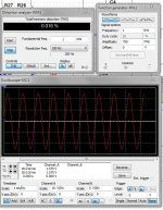
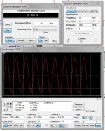
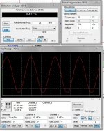
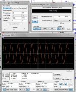
As I promised here is the simulation. On the pictures 1 , 10 and 20 kHz and THD.
Not very different from your results so you need to choose a different topology probably. I played a bit and tuned the schematic but was unable to get lower than 0.3% THD at 20kHz.
P.S. In my database there is no STE47N50 so I used IRFP250.
Regards!
Not very different from your results so you need to choose a different topology probably. I played a bit and tuned the schematic but was unable to get lower than 0.3% THD at 20kHz.
P.S. In my database there is no STE47N50 so I used IRFP250.
Regards!
Attachments
I had to use a model for IRFP240 as there are none for these STE fets that i know of.
Anyways i wired up two channels of this amp with the circuit you simulated and it does actually sound pretty good. I reduced the gate resistors to 91 ohms from 940 ohms.
Btw i've tried simuylating a few different topologies, including yours to no avail, all gives the same results. :/
Anyways i wired up two channels of this amp with the circuit you simulated and it does actually sound pretty good. I reduced the gate resistors to 91 ohms from 940 ohms.
Btw i've tried simuylating a few different topologies, including yours to no avail, all gives the same results. :/
Cascoded or EF VAS cannot fix this: http://i.imgur.com/g8dm0.png
Despite 100mA bias, the simulation thinks one fet closes way before the other opens, only a N channel output stage simulates like this, the P channel amp and all bjt topologies simulates properly with thd below 0.05% at 20kHz. with the exact same frontend.
Heres a video of the actual amp: NMOS amp in stereo - YouTube
R14 and R15 are in the wrong place and do nothing except burn power. R14 needs to move down to R16/R20 and R15 move up to R10/M2.
The drivers need to run at much higher current because of the big gate capacitance. This may help your distortion, but the quasi topology does suffer inherently worse distortion than complementary anyway.
Your amp may sound OK to you, but the VAS needs to be much stronger with such big capacitance to drive. I don't think 6 pairs is feasible without some kind of quite heavy duty buffer stage either.
It would be three pairs per channel, not six.
In all quasi designs i've seen, the "source resistors" are always placed at the source terminal of the output fets.
I increased the current in the drivers(something i tried before to no avail) but this time it worked!
http://i.imgur.com/niUUx.png
I do also have boards with a beta enhanced VAS(EF coupled)
Nice! Now you can try increasing the VAS current and of course changing the VAS device to a more powerful one and will get even better results.
Next 4-5 days I will go to a little vacation so will not visit the forum. Will be very curious about your final result.
Regards!
Next 4-5 days I will go to a little vacation so will not visit the forum. Will be very curious about your final result.
Regards!
I've seen ppl use MJE340/350 for VAS, but i've never had any luck in my simulations, i've always had the best results with a 2N5401/5551 VAS.
This is with MJE350 VAS running at 1 watt, using the save resistor values as quasi did: http://i.imgur.com/hx58y.png
Notice thats its actually 0.004% THD worse than my 2N5401 VAS.
Notice thats its actually 0.004% THD worse than my 2N5401 VAS.
Now i have this circuit up and running on one channel: http://i.imgur.com/GcRco.png
The drivers are now running nice and hot, and its hard to tell if its sounding any better but i think it might be sligtly brighter than the other channel which is still running the low driver current.
The drivers are now running nice and hot, and its hard to tell if its sounding any better but i think it might be sligtly brighter than the other channel which is still running the low driver current.
take care of oscillation when install the diode. With diode you've to add a compensation capacitor between base and collector of that driver.
Don't know if will improve your sound. If you say "no", i trust you 😛
Don't know if will improve your sound. If you say "no", i trust you 😛
The diode brings up THD in my simulation from 0.033% without it, to 0.4% with it, it also affects bias to the point where it has to be reset.
This is the circuit i am currently listening to: http://i.imgur.com/z7i8h.png
Its sounding pretty sweet 😀
This is the circuit i am currently listening to: http://i.imgur.com/z7i8h.png
Its sounding pretty sweet 😀
- Status
- Not open for further replies.
- Home
- Amplifiers
- Solid State
- Revisiting the NMOS amplifter