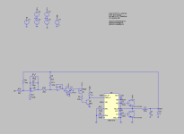
Hi everyone! I'm fairly new to the world of DIY audio and very new to Class D amplifiers. Perhaps a little ambitious for my first undertaking, but I'd like to build a UcD derivative with GanFETs and ICs instead of the slower-switching, original discrete design. I use the higher order feedback network referenced in Putzey's paper to obtain greater phase offset and thus higher oscillation frequency. I'd love some feedback on my simplified schematic as well as advice moving forward in the design process. Please forgive any blatantly novice mistakes, and thank you in advance for your comments!
Attached below are the necessary simulation files as well as the small signal model of the filters for calculating oscillation frequency.
Attached below are the necessary simulation files as well as the small signal model of the filters for calculating oscillation frequency.
Attachments

No he doesn't, the load reference is mid-rail (V3,V4) - the arrow is a different shape.
I'd be a bit concerned about the turn-off time of Q2, there's nowhere for stored base charge to go. How does that look in the transient sim?
I'd be a bit concerned about the turn-off time of Q2, there's nowhere for stored base charge to go. How does that look in the transient sim?
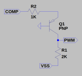
The LMG1210 model broke for some reason if I didn't use ground as HV- so COM is my reference and GND is HV-You have DC current in the load, a series capacitor is needed.
The transient sim shows about 15ns turn on and turn off, but I'm using a perfect PNP so maybe its not picking up on it. I'd love other suggestions for low power consumption negative level shifters that are fast enough though!No he doesn't, the load reference is mid-rail (V3,V4) - the arrow is a different shape.
I'd be a bit concerned about the turn-off time of Q2, there's nowhere for stored base charge to go. How does that look in the transient sim?
In that circuit, what two voltages is COMP swinging between?This
It is tied to the output of your comaparator.
If your comapator swings +/-5V you put 5V-0.6V across the 1K resistor the resulting current appears in the 2K resistor so you get a 10V-1,2V swing at your pwm input.
Adjust the values to suit your needs.
You might wish to put a diode base-emitter, bar end on emitter, to prevent breakdown but ideally it should not be necesary.
Last edited:
Your opening has contradictions. "fairly new", "build a UcD derivative with GanFETs and ICs instead of the slower-switching, original discrete design. I use the higher order feedback network referenced in Putzey's paper to obtain greater phase offset and thus higher oscillation frequency."
Your first task is to make it self oscillate at a target frequency, Does it oscillate ?
Your first task is to make it self oscillate at a target frequency, Does it oscillate ?
Would a high quality capacitive digital isolator work instead? I tried your configuration as well as several others, but the tradeoff between slew rate and power draw is hard to balance.It is tied to the output of your comaparator.
If your comapator swings +/-5V you put 5V-0.6V across the 1K resistor the resulting current appears in the 2K resistor so you get a 10V-1,2V swing at your pwm input.
Adjust the values to suit your needs.
You might wish to put a diode base-emitter, bar end on emitter, to prevent breakdown but ideally it should not be necesary.
My apologies, I didn't mean to make my post confusing. I'm not sure what the contradiction is between those two passages though?Your opening has contradictions. "fairly new", "build a UcD derivative with GanFETs and ICs instead of the slower-switching, original discrete design. I use the higher order feedback network referenced in Putzey's paper to obtain greater phase offset and thus higher oscillation frequency."
Your first task is to make it self oscillate at a target frequency, Does it oscillate ?
The amplifier oscillates at around 2 MHz, dropping to around 700 KHz when it's pushed close to the rails. THD simulations using the .FOUR command show good results, but I've read in other papers that these simulations aren't the most reliable for Class D. Due to each simulation taking a very long time, I've only simulated 1 Khz and 10 Khz at 1W and 600W into a static 4Ω load. I still need to verify that at clipping there are no other oscillation solutions, but it's stable with the parameters mentioned.
How does one tune a loop at 2-MHz with conventional methods?
At 500Khz and Mosfets you could do the following:
At 500Khz and Mosfets you could do the following:
- Differential modulator.
- 2nd order integrator (with Integrator anti-windup).
- Protection trips.
- Switch taming.
Honestly I played with values until I got the feedback phase shift I was looking for. Since I'm new to control theory, calculating component values from the improved oscillation criterion equation is out of my reach for now.How does one tune a loop at 2-MHz with conventional methods?
At 500Khz and Mosfets you could do the following:
- Differential modulator.
- 2nd order integrator (with Integrator anti-windup).
- Protection trips.
- Switch taming.
Would implementing these not be possible at higher oscillation frequencies? And will higher oscillation frequencies not improve THD (albeit marginally)?
As for the differential modulator, I intend to design a full bridge version if I am able to succeed with this one.
Higher order loops add complexity and challenge my already-scant knowledge of control theory further.
Would integrator anti-windup only be to tame the higher order loop at or near clipping? If so, and there isn't another oscillation solution with the current feedback loop, there shouldn't be a need for anti windup, correct?
I intend to add overcurrent protection, if that's what you mean.
And what is switch taming?
Thank you for your feedback and sorry for all the questions I'm throwing at you 🙂
H
HAYK
To link analog ground referenced signal to digital, you can use high speed opto coupler 6n135. It will isolate the signal from polluted digital ground from the analog one.
Designing cars that can accelerate from 0-60 mph in under 5 seconds presents an exponentially increasing challenge. As the desire for such speeds grows, the complexities in every field of science and engineering intensify. "2MHz, PCB Layout, GanFETs, Low THD."Honestly I played with values until I got the feedback phase shift I was looking for. Since I'm new to control theory, calculating component values from the improved oscillation criterion equation is out of my reach for now.
Would implementing these not be possible at higher oscillation frequencies? And will higher oscillation frequencies not improve THD (albeit marginally)?
As for the differential modulator, I intend to design a full bridge version if I am able to succeed with this one.
Higher order loops add complexity and challenge my already-scant knowledge of control theory further.
Would integrator anti-windup only be to tame the higher order loop at or near clipping? If so, and there isn't another oscillation solution with the current feedback loop, there shouldn't be a need for anti windup, correct?
I intend to add overcurrent protection, if that's what you mean.
And what is switch taming?
Thank you for your feedback and sorry for all the questions I'm throwing at you 🙂
It's advisable to start with an existing, functional design, such as a schematic and PCB. By building upon a proven foundation, you can avoid the pitfalls of starting from scratch. Beginning at ground zero often leads to numerous misconceptions and a maze of options, none of which may provide a clear solution.
Last edited:
May I ask a dumb question? How does this oscillate? It seems to use the inductor in the filter as some sort of integrator? I've done some sims of this, and the oscillation stops when the input signal is really small, probably due to hysteresis of the comparitor. For the ltspice in the zip file, this starts at 0.6mV, but this dependent on exact components used. (Using a different comparitor oscillation stops at 10mV input). Interesting circuit but concerned about small signals.
How does this oscillate?
Not a stupid question but it's a hard subject to master few here have the knowledge to even answer the question.
The fundamental component here is a Phase Shift Oscillator, which operates based on control theory principles. In this setup, the oscillator functions as a "system" where various elements contribute to a cumulative phase shift. These elements include the phase shifting caused by the inductor, the propagation delay from the IC driver, and the phase lag or lead introduced by the RC network. Altogether, these factors result in a total phase shift of 360 degrees. Additionally, the system's gain remains above zero (+dB).
At the heart of this system is an integrator with a double pole, which primarily determines the oscillation frequency. However, this is just the basic structure. The oscillator also incorporates several feedback loops. These loops are crucial as they enhance the system's stability under various conditions, such as during distortion recovery and in maintaining switching stability.
The deeper you delve into this field, the more you'll encounter patents featuring diverse and complex objective claims. These often extend well beyond the typical scope of a DIY enthusiast, demanding substantial expertise in control mathematics and circuit simulation. However, for most makers, a solid understanding of the basic loop structure should suffice. Additionally, there are more accessible areas where DIY enthusiasts can excel, surpassing even top market specifications. This includes leveraging microcontroller-assisted features to enhance long-term durability and PCB layout pratices.
- Home
- Amplifiers
- Class D
- Review of First Class D Design