
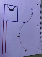
Is this how these work if I was trying to illustrate the pressure/velocity wave shape?View attachment 1459239
Driver = +90 degrees
Port = -180 degrees
Difference = 90 - (-180) = 270 degrees
View attachment 1459237
Attachments
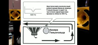
So then these things are suppose to resonate at 4 x the 1/4 wavelegth where it wants to cancel out the vent sound traveling over the driver?
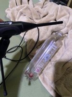
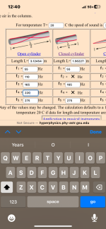
It seems so hard to get the air to move over this sufficiently and at the correct angle to generate it (with my mouth). I wonder how much air is moving in a ‘port’ (or the box if in double bass reflex series like the OP) to get it ‘going’ if you folded a 1.56 meter pipe on its self ?
It seems so hard to get the air to move over this sufficiently and at the correct angle to generate it (with my mouth). I wonder how much air is moving in a ‘port’ (or the box if in double bass reflex series like the OP) to get it ‘going’ if you folded a 1.56 meter pipe on its self ?
Attachments


Is this how these work if I was trying to illustrate the pressure/velocity wave shape?
So then these things are suppose to resonate at 4 x the 1/4 wavelegth where it wants to cancel out the vent sound traveling over the driver?
It will depend on the actual dimensions of the system, and what the designer is trying to achieve. AKABAK can be used to consider pressures and volume velocities inside the individual acoustic elements of a loudspeaker. I simply compared the phase of the signal radiating from the front side of the driver to the phase of the signal at the port output, to illustrate the comment made by Art.