Hello again, thanks to you all, I'm using some much more reliable data for x-over simulation. On to the next question.
In PCD7 simulation I have a 3-way design that only sums properly when BOTH the mid AND tweeter are polarity reversed. I get a nice, deep null (~35dB) when I "unflip" the tweeter polarity, which leads me to believe I can trust it. But I don't think I've seen this done. Should I continue or hunt for another solution? Could well be that I just don't understand crossover orders enough.
What's in the simulation:
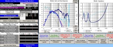
Woofer LPF is 2nd-order electrical nothing special
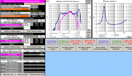
Mid HPF is 2nd-order electrical nothing special
Mid LPF is 2nd-order electrical but the "Target" is 4th-order
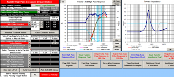
Tweeter HPF is 2nd-order electrical but the "Target" is 4th-order.
Does this mean that my mid/high X-over is 2nd-order electrical, but 4th order acoustic? Why would I do this instead of going to 4th order electrical? Still trying to tackle x-over effects on phase. . . Thanks!
In PCD7 simulation I have a 3-way design that only sums properly when BOTH the mid AND tweeter are polarity reversed. I get a nice, deep null (~35dB) when I "unflip" the tweeter polarity, which leads me to believe I can trust it. But I don't think I've seen this done. Should I continue or hunt for another solution? Could well be that I just don't understand crossover orders enough.
What's in the simulation:
Woofer LPF is 2nd-order electrical nothing special
Mid HPF is 2nd-order electrical nothing special
Mid LPF is 2nd-order electrical but the "Target" is 4th-order
Tweeter HPF is 2nd-order electrical but the "Target" is 4th-order.
Does this mean that my mid/high X-over is 2nd-order electrical, but 4th order acoustic? Why would I do this instead of going to 4th order electrical? Still trying to tackle x-over effects on phase. . . Thanks!
Nothing wrong here, there are number of successful 3-way designs with both mid and tweeter reversed. The same frequency response you can get with woofer reversed and both mid and tweeter with "correct" polarity - try it.
2nd-order electrical filter on pure resistance will generate 2nd-order acoustic filter, but loudspeaker impedance seldom is pure R, so it is normal to get 4nd-order acoustic filter as a result.
2nd-order electrical filter on pure resistance will generate 2nd-order acoustic filter, but loudspeaker impedance seldom is pure R, so it is normal to get 4nd-order acoustic filter as a result.
Last edited:
If you had a 3 way with 2nd order electrical xo's at every stage I"d normally expect to see just the mid with the reverse polarity, but there's plenty of other stuff that can happen to change that, especially between the mid and the tweeter. As long as the data is accurate for your current enclosure and sums correctly in simulation you'll be fine... By which I mean if you measure Fr & Impedance of all your drivers raw in the enclosure then let pcd7 sum them and compare it to real world summation, or apply a very basic protective crossover and compare to ensire it's right - there's always baffle step, driver spacig etc to work with.
But most importantly it sounds like you're doing fine. If you want to put a drop box link up I (and probabky other forum members) will happily take a look. Out of interest what drivers are you using and what xo frequencies?
But most importantly it sounds like you're doing fine. If you want to put a drop box link up I (and probabky other forum members) will happily take a look. Out of interest what drivers are you using and what xo frequencies?
nannoo, thanks for the reply. It's encouraging to hear that seeing as I've already ordered my second batch of X-over parts.
Drivers are in MTMW configuration:
Mids are both Tang Bang W4-1720
Tweeter is Usher 9950-20
Woofer is Dayton RS225-8
XO frequencies are (at least numerically in PCD7) 375Hz and 3kHz. I think acoustically they XO at about 500Hz and 2kHz
Here is a link to a dropbox folder that has screen shots of all my PCD sections, as well as all my FRD and ZMA data that I used.
https://www.dropbox.com/l/loAfpDw2RRcPB3dJi6lZIu
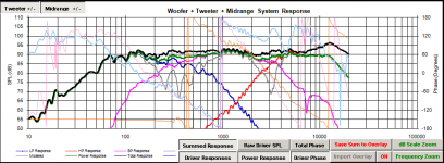
I mentioned this before, in the System Response chart, don't concern yourself with the Total Phase - turn on the Driver Phase instead. Also click on Phase in the individual driver charts as well. This will allow you to see what happens to the phase as you adjust the xo values. Resistors in the shunt line are particularly effective in this regard. I like to see the individual Driver Responses in the top chart as well.
Also, it looks like you are using the filter response instead of the target response as your guideline. This is very obvious with your mids and tweeter and I think is the reason that your actual xo points are not the same as your target xo points. So turn off the filter response in each of the separate driver charts and re-do the xo's.
Your mid response is quite peaky. Try to get it to make more of a contribution to the overall FR.
It is the acoustic responses that matters most not necessarily what order each of the xo's are. So if you can get a 4th order acoustic from a 2nd order electrical, that will mean less components in the signal path and less money out of your pocket. I tend to want to keep my LP xo's 2nd order electrical so that I don't have to put 2 inductors (and their resistances) in series with the woofer but I often go up to 3rd order electrical on the tweeter to get the steep 4th order acoustic I want and to get the phases to align.
See if you can't glean anything from this video tutorial that will help you out.
jReave, that video was great. The first thing it made me realize is that I need to use PCD7 on my PC and not my mac, cause WOW that is faster than mine.
I shot myself in the foot by ordering round 2 of XO components before watching this video. I think it really showed me application of things I knew about, but wasn't sure how to work through in PCD. Back to the drawing board, maybe I'll finish these speakers before the end of the world. . .maybe.
I shot myself in the foot by ordering round 2 of XO components before watching this video. I think it really showed me application of things I knew about, but wasn't sure how to work through in PCD. Back to the drawing board, maybe I'll finish these speakers before the end of the world. . .maybe.
Ok, I've started a fresh PCD file and here's what I landed with. The trace looks better, I'm still happy with the nulls when polarity is flipped, and it will be a cheaper XO. What's not to like?
After I took the screenshots I added in the DCR for the inductors and it didn't change much as I'm going with solid core.
Crash
After I took the screenshots I added in the DCR for the inductors and it didn't change much as I'm going with solid core.
Crash
Attachments
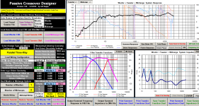
That looks better. Still, I would like to see the individual driver responses and the power response in the 1st graph. Phase looks very good in the xo regions now (I think you've got it 😉) but it wouldn't hurt to see the reverse nulls too (change the mid polarity, hit 'Save Sum to Overlay' and then change the mid polarity back). All together it will look like the chart below, a little bit messy maybe but you kind of get use to it.
I also want to keep my eye on impedance while I'm working on each individual xo - so hit the LP, HP and BP buttons for the different drivers in those charts. I doubt it will be a problem but your impedance is hitting down to about 4ohm between about 2k and 3kHz. You want to keep your eye out for where it might be dipping too low for your amplifier.
I might start off trying just a little more resistance on the mid and the tweeter but that's really what your final listening tests will be for. I'm hoping you know how capacitors and resistors sum when in series and parallel because this can help you out in xo tweaking without having to order new parts all the time. Buy a number of smaller values of resistors and capacitors and then add together to get the values that you need (eg, something like 25+5+5=35uF or 4+1+1=6uF and so on) and then you can fine tune by adding or subtracting things.
One other thing I might try is on the woofer, try to see if you can reduce that inductor and raise the capacitor. It might save you some money and some series resistance.
Attachments
Sorry I forgot to include that data. Here it is. And I don't know why I didn't think to buy smaller pieces and add/subtract to tweak. It's so simple!
I agree with you on adding resistance to mid/tweeter. Where I come from (live sound) the end trace tilts down as you go up in frequency by about 6dB to sound "flat" and these speakers are for and old live sound vet so I think you're right about just playing that one by ear (pun).
I didn't enter in the exact VC diameters so I'm not sure how accurate the power response is.
PS. Thanks a ton for your help with this. I've come a long way up a steep curve this week. This is a great community, is it not?
Attachments
- Status
- Not open for further replies.
- Home
- Loudspeakers
- Multi-Way
- Reverse Tweeter Polarity in a 3-way?