Hello! I'm new here, and new to audio in general. This is my first post, and I hope to give back as much as I take.
I recently inherited some vintage hi-fi equipment, including a pair of EICO HFS-2 speakers designed by Stewart Hegeman. If you don't know about them, you can read about them here: Citation X and Eico HFS-2 Speaker Systems
I've seen a lot of interest in these speakers, and I find Stewart Hegeman and his ideas deeply fascinating. Since I have been given this extremely rare and unusual piece of hi-fi history, I feel compelled (almost obligated) to try to "figure them out" and share what I learn.
To that end, I'm in the process of reverse engineering a pair of EICO HFS-2 speakers.
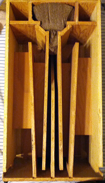
I'm currently measuring the "double section slot-loaded conical horn" that makes up the bottom of the speaker. I have disassembled the rear of one cabinet and taken measurements (don't worry, I dissected the speaker with the care of a plastic surgeon). Here is a photo :
My problem is, I don't know how precise I should be.
My immediate instinct was to pull out my calipers and measure down to the thousandths of an inch. But it seems to me that in doing so, I'm introducing false precision. Hegeman created a design with a certain level of precision, and EICO built it with some allowable margin of error. I'd like to see past the "margin of error" to - as best as possible - find the designed measurements.
For instance, take the mouth of the horn.
If I pull out my calipers and measure at several locations, I'll get an average measurement of 1.346 inches at the opening. So I ask myself, did Hegeman ask for 1.35 inches and the .006 deviation fell in the margin of error? Or did he ask for something like 1.3 inches or maybe 1-3/8" or maybe 1-15/16".
See my dilemma? I don't know which figures are significant.
Any insight or guidance would be helpful, but here are a few specific questions:
1.) In the design of folded horns, how precise do you need to be to get the proper results? For instance, would a deviation of 1/64th of an inch in a 4 inch horn mouth make a measurable or audible difference? 1/8th? What level of precision matters?
2.) If you were Stewart Hegeman working for EICO and you were designing this speaker, what system of measurement would you probably use? Imperial? Metric? Any insight or guesses?
3.) Finally, what would your guess on precision be? If you had to guess, would you say Hegeman wrote his measurements down to the 64th, 32nd, 16th, 8th (or if metric: cm, mm, micrometer, nano-meter)?
Like I said, any suggestions or insight would be helpful. If you think I'm going about this all wrong, or have a better way of doing this, let me know!
Thanks!!!
I recently inherited some vintage hi-fi equipment, including a pair of EICO HFS-2 speakers designed by Stewart Hegeman. If you don't know about them, you can read about them here: Citation X and Eico HFS-2 Speaker Systems
I've seen a lot of interest in these speakers, and I find Stewart Hegeman and his ideas deeply fascinating. Since I have been given this extremely rare and unusual piece of hi-fi history, I feel compelled (almost obligated) to try to "figure them out" and share what I learn.
To that end, I'm in the process of reverse engineering a pair of EICO HFS-2 speakers.
I'm currently measuring the "double section slot-loaded conical horn" that makes up the bottom of the speaker. I have disassembled the rear of one cabinet and taken measurements (don't worry, I dissected the speaker with the care of a plastic surgeon). Here is a photo :
My problem is, I don't know how precise I should be.
My immediate instinct was to pull out my calipers and measure down to the thousandths of an inch. But it seems to me that in doing so, I'm introducing false precision. Hegeman created a design with a certain level of precision, and EICO built it with some allowable margin of error. I'd like to see past the "margin of error" to - as best as possible - find the designed measurements.
For instance, take the mouth of the horn.
If I pull out my calipers and measure at several locations, I'll get an average measurement of 1.346 inches at the opening. So I ask myself, did Hegeman ask for 1.35 inches and the .006 deviation fell in the margin of error? Or did he ask for something like 1.3 inches or maybe 1-3/8" or maybe 1-15/16".
See my dilemma? I don't know which figures are significant.
Any insight or guidance would be helpful, but here are a few specific questions:
1.) In the design of folded horns, how precise do you need to be to get the proper results? For instance, would a deviation of 1/64th of an inch in a 4 inch horn mouth make a measurable or audible difference? 1/8th? What level of precision matters?
2.) If you were Stewart Hegeman working for EICO and you were designing this speaker, what system of measurement would you probably use? Imperial? Metric? Any insight or guesses?
3.) Finally, what would your guess on precision be? If you had to guess, would you say Hegeman wrote his measurements down to the 64th, 32nd, 16th, 8th (or if metric: cm, mm, micrometer, nano-meter)?
Like I said, any suggestions or insight would be helpful. If you think I'm going about this all wrong, or have a better way of doing this, let me know!
Thanks!!!
Given the realities of manufacture, 1/8" is probably sufficient, but i'd do 1/16" (actually i would do to the mm)
dave
dave
Thanks for your input, planet10.
The thing that gets me about the speaker is that I have reason to believe there might be designed differences of as little as 1/32 of an inch between the two halves of the horn.
Take a look at the far left and far right bracing. See how the brace on the right is lower than the brace on the left? When I first saw it, I assumed it was just a result of the margin of error. But... If you look at the article about these speakers here.
You will see that in the cut-away of the speaker on the second page, that same brace is in the same position. Is that a coincidence, or is it designed?
When I measured, I found that the braces are cut to the same size. However, the angle of the plywood that makes up the final part of the horn on the right is angled such that it is 1/32 of an inch closer to the outer wall of the cabinet (measured from the top tip of the plywood to the wall of the cabinet) than the corresponding piece on the left. That resulted in the need to place the brace lower on the right half of the horn than on the right half.
It seems quite possible that all the speakers are slightly asymmetrical, given that to make them symmetrical (which is the only way to make the height of the braces match), you would need to have very tight tolerances. But then again, it's also possible (or at least I think it might be) that it was designed that way.
If I knew whether 1/32 of an inch could make a difference in a horn, and if I knew whether building a speaker cabinet with tolerances of < 1/32" was common, I would easily solve this myself. But I have no knowledge of horn design. So I'm hoping you all can help me.
That said, can I put you in the "it wasn't designed that way" camp, or do you think there might be something to this?
I know that this is an old post but I am curious as to what became of this. I used to be Dennis Boyle of Chimera Labs gofer. in exchange I got tube, vintage gear and new design knowledge.
Dennis bought one of these speakers and UPS busted it all up. I therefore got a good look at the insides as well as how the driver and its dispertion cones worked. The tweeter section for instance was controled by 2 foil/paper cones that rotated in the wizzer section of the driver. The paper had been folded round into a cone and the corners were left sticking up. By turning the cones around you could control where the highs would be directed and the cones themselves acted as part of the tweeter because of the foil and because of the conical shape made for a 360 dispertion of the mids from the speaker cone.
Dennis thought that the empty sections in the horn were resonant
chambers and that the tuning of them was the way to get around problem of error in the design. As far as I know these were never kits but were delivered assembled so if the resonance chambers were indeed used to tune each horn then variation in the building and drivers
used could have been adjusted for as they were built.
It was and is a great piece of horn design and with the DIY work on Walsh tweeters the use of the wizzer could now be done much better.
Thatch
I know that this is an old post but I am curious as to what became of this. I used to be Dennis Boyle of Chimera Labs gofer. in exchange I got tube, vintage gear and new design knowledge.
Dennis bought one of these speakers and UPS busted it all up. I therefore got a good look at the insides as well as how the driver and its dispertion cones worked. The tweeter section for instance was controled by 2 foil/paper cones that rotated in the wizzer section of the driver. The paper had been folded round into a cone and the corners were left sticking up. By turning the cones around you could control where the highs would be directed and the cones themselves acted as part of the tweeter because of the foil and because of the conical shape made for a 360 dispertion of the mids from the speaker cone.
Dennis thought that the empty sections in the horn were resonant
chambers and that the tuning of them was the way to get around problem of error in the design. As far as I know these were never kits but were delivered assembled so if the resonance chambers were indeed used to tune each horn then variation in the building and drivers
used could have been adjusted for as they were built.
It was and is a great piece of horn design and with the DIY work on Walsh tweeters the use of the wizzer could now be done much better.
Thatch
Hello Thatch! You can read about the design ideas behind the HFS-2 in the article linked below. Hegeman wrote about them in great detail:
Eico HFS-2
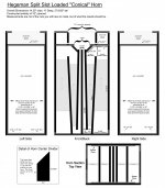
After many hours of measuring and research, I finalized a drawing of the cabinet and put together all the information one would need to make an extremely accurate recreation of this design -- right down to the glue, paper, and metal used to make the "lilly tweeter" and "boat whizzer" cones.
I attached the cabinet plan to this post if you're interested in it. I can share the rest of the information (the drivers that were used and how they were modified) if you'd like.
Attachments
- Status
- Not open for further replies.