Frankly I don't know yet if what follows is a pretty crazy idea, but at least I want to share it trying to make it happen...
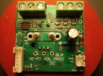
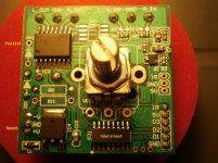
Please let me know if I'm breaking any rule, but I found the digital volume in the pictures in attachment to replace a stereo potentiometer: the sound is good, but the supporting electronics (remote control, up/down counter and 7-segment display) is poor.
So, since in the past I saw some experts who only needed to analyze a circuit in order to understand and replicate its scheme, I thought to ask for help the experts of this great Forum in order to possibly re-design those parts of the project that are poor, even in a modular way (if/when possible).
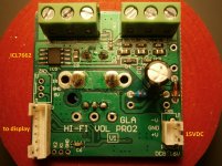
The board is powered with 15VDC and the remote control unit is for volume + and volume + and for mute (and that's enough for me), but when the keys are pressed the up and down count is jerky in the sense that it is not accurate (sometime it is slow, other times it is too fast).
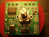
Furthermore, as described in another thread opened by myself here, the number 1 of both the 2-digits is on the wrong side of the display (on the left side) and it is quite odd to see.
If some expert wanted to accept this challenge I would be very pleased to be able to give both all my support and enthusiasm: thank you very much!
Please let me know if I'm breaking any rule, but I found the digital volume in the pictures in attachment to replace a stereo potentiometer: the sound is good, but the supporting electronics (remote control, up/down counter and 7-segment display) is poor.
So, since in the past I saw some experts who only needed to analyze a circuit in order to understand and replicate its scheme, I thought to ask for help the experts of this great Forum in order to possibly re-design those parts of the project that are poor, even in a modular way (if/when possible).
The board is powered with 15VDC and the remote control unit is for volume + and volume + and for mute (and that's enough for me), but when the keys are pressed the up and down count is jerky in the sense that it is not accurate (sometime it is slow, other times it is too fast).
Furthermore, as described in another thread opened by myself here, the number 1 of both the 2-digits is on the wrong side of the display (on the left side) and it is quite odd to see.
If some expert wanted to accept this challenge I would be very pleased to be able to give both all my support and enthusiasm: thank you very much!
Attachments

I think it's just a microcontroller reading data from an encoder and an ir receiver and passing it trough to a digitally controlled potentiometer ic thing.Wouldn't be hard to reprogram or redesign if you are familiar with programming for microcontrollers.
I think it's just a microcontroller reading data from an encoder and an ir receiver and passing it trough to a digitally controlled potentiometer ic thing.Wouldn't be hard to reprogram or redesign if you are familiar with programming for microcontrollers.
Thanks for your appreciated reply, but I don't even know where to start although I may learn quickly.
I thought about a rough idea that then could become more concrete with the contribution of the experiences of those who have maybe already achieved such a thing or a part of that and then put things together...
We can recognize Burr Brown logo on the analog chip it’s likely to be a pga2320 2311 or 2310 as it has a 16 pin package.
http://www.ti.com/audio-ic/amplifiers/volume-control-ics/products.html
IC4 looks like a 5v regulator made by ST, the PGA seem to be powered with a single rail Zeneca stabilised, no regulator : poor choice
No marking on IC3...hard to identify...maybe a cheap ST STM8 uc.
Your project looks like this one with a pga2311, an arduino and a lCD :
Arduino CPU for the PGA2311 preamp
ulogon,
Can you read the part numbers on the chips? It is probably very dependent on lighting. A small flashlight held a low angle relative to a chip might be helpful.
Can you read the part numbers on the chips? It is probably very dependent on lighting. A small flashlight held a low angle relative to a chip might be helpful.
Many thanks to both of you!!
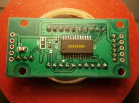
The following is the ICs list:
IC1 JXI5020GF MBI|MBI JXI5020GF-B|LED Drivers|Lcsc
IC2 PGA2310
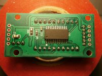
IC3 label erased (16 pins)
IC4 78M05 https://www.st.com/resource/en/datasheet/l78m.pdf
IC5 ICL7662 https://datasheets.maximintegrated.com/en/ds/ICL7662-Si7661.pdf
And new pictures with added infos in attachment.
The following is the ICs list:
IC1 JXI5020GF MBI|MBI JXI5020GF-B|LED Drivers|Lcsc
IC2 PGA2310
IC3 label erased (16 pins)
IC4 78M05 https://www.st.com/resource/en/datasheet/l78m.pdf
IC5 ICL7662 https://datasheets.maximintegrated.com/en/ds/ICL7662-Si7661.pdf
And new pictures with added infos in attachment.
Attachments
PGA2310 Stereo Audio Volume Control
http://www.ti.com/lit/ds/symlink/pga2310.pdf
What is missing is an MCU or equivalent for reading the rotary encoder and writing commands to the volume control chip (SPI bus interface).
To see if the IC with no markings is an MCU, trace out where its pins go to on the other chips. Sketch out your own schematic diagram of how things look to be interconnected.
Generally speaking the dot or dimple on top in one corner of an IC denotes pin 1. From there the other pins are counted going counterclockwise if looking at an IC from the top. From the bottom side it goes clockwise starting from pin 1.
Last edited:
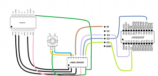
Nice diagram. Unmarked part sure looks to be an MCU or something similar used to read the rotary encoder, set the volume, and operate the display (and perhaps read an infrared receiver for remote control, likely located on the display board).
That unmarked chip is likely where your problem is, unless perhaps there is a power quality problem causing glitches. It also means that to fix it you would probably need to program another MCU to replace the unmarked one.
That unmarked chip is likely where your problem is, unless perhaps there is a power quality problem causing glitches. It also means that to fix it you would probably need to program another MCU to replace the unmarked one.
Last edited:
The fun part is reading the IR signals.
Its usually bursts of pulses (cant remember the frequency now)
I did some IR work for a surveillance system with four cameras.
I had to read in IR for start and stop record from the remote.
Then had to play them back to start/stoop VCR.
It had to be reliable.
Its usually bursts of pulses (cant remember the frequency now)
I did some IR work for a surveillance system with four cameras.
I had to read in IR for start and stop record from the remote.
Then had to play them back to start/stoop VCR.
It had to be reliable.
Thanks!Nice diagram.
I can confirm both all the above described features of the board and all the related functions of the MCU with label erased (16-pins - 10mm x 4mm): it reads the rotary encoder, it sets the volume, it operates the display and it reads an IR receiver located on the display board.Unmarked part sure looks to be an MCU or something similar used to read the rotary encoder, set the volume, and operate the display (and perhaps read an infrared receiver for remote control, likely located on the display board).
I do not think about a power issue since the needed 15VDC are supplied by a 5A commercial linear regulated power supply (thoroidal) good for audio.That unmarked chip is likely where your problem is, unless perhaps there is a power quality problem causing glitches.
Yep, but now the real question for me is: which one?It also means that to fix it you would probably need to program another MCU to replace the unmarked one.
How to find a MCU with same pinout in order to replace the "old" one?
Thank you very much!
Don't know which brand MCU they used, but ST brand parts are used on a lot of Chinese boards sold on ebay. You might look around at: Microcontrollers (MCU) and Microprocessors (MPU) - STMicroelectronics
...Otherwise if no luck, you might need to make an adapter or put an MCU on a small separate board electrically attached with a ribbon cable.
Also, if you do have luck looking around at ST (or other MCU manufacturers), you might try to reprogram the MCU you have now just to see if it is in fact one of theirs. It usually takes access to the Reset pin and the SPI port pins, IIRC.
It’s not a ST STM8 nor STM32 family because they do not have parts with 16pin package. (Search for ´ST MCU finder’ app on Android or Apple AppStore to get full product catalog with parametric search)
In addition this chip is 5v powered...maybe a former ATMEL or microchip or...who knows..
You could try to unsolder the chip connect the pin identified on your schematics to an arduino and start an arduino project to manage the IR the display and the PGA
Chris
In addition this chip is 5v powered...maybe a former ATMEL or microchip or...who knows..
You could try to unsolder the chip connect the pin identified on your schematics to an arduino and start an arduino project to manage the IR the display and the PGA
Chris
Yep, I thought the same and also that it must be a (very) cheap part.It’s not a ST STM8 nor STM32 family because they do not have parts with 16pin package. (Search for ´ST MCU finder’ app on Android or Apple AppStore to get full product catalog with parametric search)
In addition this chip is 5v powered...maybe a former ATMEL or microchip or...who knows..
You could try to unsolder the chip connect the pin identified on your schematics to an arduino and start an arduino project to manage the IR the display and the PGA
Chris
My sensation is that it could be the following item since both the pins number and the size match:
5pcs 15W402AS STC15W402AS-35I-SOP16 SOP16 | eBay
But who knows?
Furthermore I do not know neither Arduino nor MCU programming although in the recernt past I programmed a PIC IC for an IR receiver...
Last edited:
- Home
- Source & Line
- Digital Line Level
- Reverse engineering for this project