Hi Merlinb. I can't seem to find this tank online - is the code correct? CHeersSounds like the driver coil is burned out, but the recovery coil is still OK.
Since you're restoring the amp I wouldn't start rebuilding a completely new driver, especially not a bulky expensive Fender copy. Just buy a new tank: Accutronics 8GB2C1G is drop-in replacement for this type of circuit.
Failing that, replace V6 with an ECC81, change R20 to 10k 1W, bias the driver for about 5mA, and hook up to a type F tank. You can reduce R44 to get a higher supply voltage if necessary.

Thanks MerlinB. I have been given another spare reverb tank - do you think this would work ... ? https://reverb.com/uk/item/3630910-reverb-tank-bl3eb3c1b-2012-black-silver
It is only 800 ohms input impedance, so it will not work in the ECC83 circuit as-is (or it will be extremely faint). But if you convert to an ECC81 as I described earlier, it should work well.
Hi again Merlin. I put the BL3EB3C1B Belton tank in with a ECC81 for the driver at V6, and the 10K anode resistor for R20. No reverb coming through. I measured the cathode voltage and it was 2V with 1855 ohms measuring on the cathode resistor (R21). This makes only about 1mA of current. The plate voltage was very low - only 135V. Should I try a lower value cathode resistor for R20 (I have an 820R or a 270R - not sure which would give me 5mA) or change R44 to try and get a higher plate voltage or maybe I need to do both...? Cheers. TomIt is only 800 ohms input impedance, so it will not work in the ECC83 circuit as-is (or it will be extremely faint). But if you convert to an ECC81 as I described earlier, it should work well.
So I replaced R20 with 10K and R44 with an 820R but I'm still getting no reverb and very low voltages everywhere. Can't quite work out why this is. I have 341V coming off the rectifier (seems OK), 313V between R46 and R46, 257V at A but then everything else on the HT rail is low: B is 148V, C is 142V now that R44 is 820V, and D is 56V!!! Surely this can't be right!. This is with the ECC81 installed at V6 and R21 replaced with 270R. I was thinking something may be wrong with R46 but I can't seem to measure it in situ as the value keeps changing.Yes you need a lot more current, and to get there you will need more supply voltage (like 200V or more).
Change the cathode resistor to 270R, and R44 to something in the 1k to 3k range (you can just tack a resistor in parallel).
The previous post should have said "313V between R46 and R47"
Actually it kind of does make sense as the lower value at cathode resistor R21 (now 270R) means more current firing through V6 which is upping the current flowing through R46 so causing a much bigger voltage drop. So I'm thinking I need to take the C rail for the driver before R46 (i.e. between R46 and R47) with a jumper and forget about R44 and it's associated power cap - would this work or is it just plain stupid?
Actually it kind of does make sense as the lower value at cathode resistor R21 (now 270R) means more current firing through V6 which is upping the current flowing through R46 so causing a much bigger voltage drop. So I'm thinking I need to take the C rail for the driver before R46 (i.e. between R46 and R47) with a jumper and forget about R44 and it's associated power cap - would this work or is it just plain stupid?
I've never encountered an EF86 valve before but I can't believe that a plate voltage of around 50V is correct. I'll try swapping in some 10K resistors (need to order some more!) Do you think the idea was to limit the power demands on the transformer? Also I think a lot of these resistors are 10-15% higher than shown on the schematic due to their age which is probably not helping much!
Here are some cathode resistance and voltage measurements that I took...(attached). It does kind of make sense as I calculated the total current through V1,V2,V3 and V6 (B, C and D) is almost 5mA which accounts for the 167V drop across R46 (33K).
Attachments
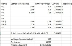
But you also said:I calculated the total current through V1,V2,V3 and V6 (B, C and D) is almost 5mA
B is 148V,
C is 142V,
Across an 820R resistor that's 7mA for the ECC81, so something doesn't add up somewhere.
Yes I see what you mean! I think I need to double check the measurements and also check the my circuit against the schematic. It wasn't an official one so there may be a mistake as you say!
Looks like the circuit diagram is actually correct. I've replaced the resistors with 10k s. Just waiting for some coupling caps before I retest as I reckon at least one was dodgy.
 Relocated to Instrument & Amps forum per forum policy. Guitar amp folk hang out here so you may get some additional insights.
Put in the new coupling caps around the reverb tubes and with the 10k resistors in the power chain instead of higher values we are getting better voltages all round and we are now getting some reverb. Not a great deal but it is working - thanks Merlinb for all the help! I have a 680R cathode resistor on the 2nd stage of V6 and that has upped the current.
The overall sound is a bit distorted so I reckon I need to check the biasing on the power valves and failing any issue there, recheck the signal chain going in. But all round we are definitely making progress here!
The overall sound is a bit distorted so I reckon I need to check the biasing on the power valves and failing any issue there, recheck the signal chain going in. But all round we are definitely making progress here!
- Home
- Live Sound
- Instruments and Amps
- Reverb tank solution needed for vintage British guitar amp...