I built the first half of this ckt, gave it 300 vdc, got the 4.2 v and 23mA, but no gain. Is on a breadboard, didn't have 43Vp-p in, only a couple volts from my sig gen, but with pot up gain was around unity... Should this be expected? I don't have much SS experience (I'm building it for my tube clone amp). I thought the pre circuit boosted the signal. I do expect the recovery side to boost. Need some help! Thanks
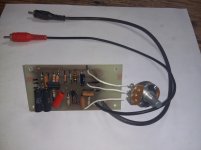
Attachments
So you should have posted down in the instruments section...
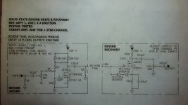
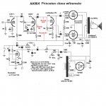
No gain? or no output level? Not the same thing. This expects 40vpp of input and you fed it 2v, so I don't imagine much comes out. Note after the volume control there is a 33/1 voltage divider comprising the 1M and the 33k resistor. So your 2v becomes maybe 60mv hitting the FET gate. If the FET were a 12AX7, that voltage division wouldn't change.
No gain? or no output level? Not the same thing. This expects 40vpp of input and you fed it 2v, so I don't imagine much comes out. Note after the volume control there is a 33/1 voltage divider comprising the 1M and the 33k resistor. So your 2v becomes maybe 60mv hitting the FET gate. If the FET were a 12AX7, that voltage division wouldn't change.
Thanks ENZO. I got the same 2Vp-p out that I put in...unity gain. I wanted to test the circuit on a bb before hard wiring it on perf. I'm gonna assume it's working. I could bypass the divider, but expect the gain to stay the same. Is this common for the reverb "pre" stage?
And, I thought about posting in Inst, but this seemed a purely SS question. Glad you found it!
And, I thought about posting in Inst, but this seemed a purely SS question. Glad you found it!
Considering 1MOhm feedback resistor between drain and gate and 1MOhm series gate resistance unitiy gain is the max to be expected.Thanks ENZO. I got the same 2Vp-p out that I put in...unity gain. I wanted to test the circuit on a bb before hard wiring it on perf. I'm gonna assume it's working. I could bypass the divider, but expect the gain to stay the same. Is this common for the reverb "pre" stage?
And, I thought about posting in Inst, but this seemed a purely SS question. Glad you found it!
Reduce gain series resistor, add a coupling capacitor and wire the pot in a normal fashion, this might help this crappy circuit to work.
I am not sure how crappy it is, it was designed for use in a particular context electrically. removing it from that context might make it less desirable.
It may be purely SS, but so is an SS guitar amp. How many spring reverbs do we find in home stereo systems?
Note that the driver is meant for an FB type pan, the highest input impedance available, so don't try to drive a typical Fender AB type pan with it.
Just for test, shunt across that series 1M from the pot, so you get a whole volt or two at the gate. See how it amplifies then. That would be more or less the same gate signal level as the intact circuit sees with the 40v signal.
Hi Guys
It does not really matter that the input impedance of the delay line is high-z inasmuch as ANY tank does not require very much input power and thus not much drive voltage. Even if the tank had a 2k z-in, at 100mW this is 14V. With direct drive, as this circuit is, a high-z tank has the advantage of not requiring too much current from the B+. However, at the 14V signal into 2k, 7mA is needed. In reality, the drive into your tank will be much lower.
As TUT details, there is about 40dB of mechanical loss through most delay lines. Therefore a hefty amount of gain is needed to recover the signal and boost it to line level. The best reverbs have two stages of recovery gain.
If you feed the generator signal into the drive stage directly and look at the recovered output, hopefully the input and output signals are about the same size - unity gain. Any reverb circuit block and effects loop block should be unity gain overall.
The 1M feedback resistor in the driver does double duty as FB and as part of the bias network for the mosfet. The gain of the drive circuit is simply unity but inverting.
Have fun
Thanks Enzo and Struth - I will shunt the 1M to simulate a higher signal, but be OK with not much gain. I have bought the same tank the schematic indicated. Can I power both pre and recovery circuits from the same HV B+ source from the tube amp?
Hi Guys
The purpose of the mod is to add reverb to a tube amp without having to add a tube. Therefore it is designed to be powered from the plate supply. As is typical with most amateur mods, there is no decoupling provided within the mod. Connecting both sections as is to the same supply node might lead to some instability if the preamp is tied to that same node. Ideally, a new supply node would be introduced between the one for the splitter and the one for the preamp. Or, this circuit can be decoupled on its own.
There is not much risk of the two reverb stages interacting with each other since the recovered signal has random phasing. Rather, it is the potential interaction of the driver with other stages that should be considered.
As noted above, the input level control should be reversed and be wired as a normal volume pot would be. How it is now, when the pot is at zero it imposes a significant treble rolloff on the preamp.
Not sure what you mean by "bypassing the 1M" but if it suggests eliminating the series 1M between the mosfet gate and the input level control, that would not be wise. Something that would be wise though would be to move the 10nF input cap to be in series with the 1M after the pot. There is a couple of volts DC on the mosfet gate and this will make the pot "scratchy" as it is wired.
Have fun
It is normal to feed the reverb tank with full power at all times and only have a volume control on the recovery side. The reason for this is cabinet vibration causing more noise than a low power drive.
I take it you are using a high impedance drive coil on the send part of the tank. There is a choice from 16R to 600R depending on the make of tank. A transformer will be better employed rather than a load resistor.
It should be mentioned that primary impedance is inductive, thus rises proportional to signal frequency. Stated impedance refers to 1kHz.I take it you are using a high impedance drive coil on the send part of the tank. There is a choice from 16R to 600R depending on the make of tank. A transformer will be better employed rather than a load resistor.
For best results, the primary coil should be current driven.
And it is a good idea to put a high level (some 100mW) into it thus reducing noise and feedback problems.
An accurate driver excites the spring enough to produce audible noise when driven with music.
Well, the design *is* poor, on many counts.
1) it's terribly inefficient.
3.5W drive FET dissipation for 100mW actual drive to the tank? Wow !!!!!
2) as noticed by Jon Snell, the actual front panel mounted "reverb" pot should be the one on the recovery side; the one on the drive side should be labelled "drive" , set once for optimum drive without clipping and left there, so in fact it should preferrably be an internal screwdriver adjustable trimmer pot, no need to bring it to the front.
3) the drive pot wiring is horrible, it's backwards, as is when set to low values it will short previous plate to ground and/or kill all mids/highs turning sound into mud (.01uF cap from plate to ground).
4) as is and expressly said in the instructions, it should go straight to a tube plate ... with some 150-250VDC on it ... which will be DC loaded by the 1M resistor to ground . WTF?
5) they should add a 1M ground reference gate resistor to LND150 ; as is pulling the reverb tank for any reason will leave it unbiased and fully saturated.
The suggestion of shorting the series 1 meg was only made as troubleshooting. Not as a suggested change. The circuit expectd 40v of input, which his generator could not provide, but the 1 meg voltage divider resistor dropped that way down at the transistor. BY bypassing the 1 meg, his low voltage signal generator could provide a realistic signal level for the remainder of the circuit.
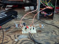
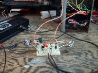
All good suggestions, thanks! I'm glad I'm breadboarding this circuit. Am learning lots from you guys. Will post revised circuit(s) as I build and test.
It works! Finally finished breadboarding it, fired up the amp, no smoke,,,, and reverb! But I want more.... will optimize the drive (within specs). Noticeable treble cut when I rolled off the recovery pot (have heard of that happening, will revisit for fixes). The 15KR's dropping the B+ on the drive side do get hot.... a lower B+ from somewhere else in the amp and I could eliminate them?
Attachments
Reverb Tank question
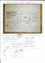
Well, I got the circuit working on a breadboard, but when I put it on a pcb it doesn't... I checked everything 3x, wish I'd documented voltages on the working setup... I measured DC ohms on the tank (checking everything!), and only got 200R in and 225R out. Should be 1475 and 2250. Is this impedance? Would it be that much different? Are tank xfmrs that delicate? I may have popped one of the semiconductors, am ordering more. Thanks!
Well, I got the circuit working on a breadboard, but when I put it on a pcb it doesn't... I checked everything 3x, wish I'd documented voltages on the working setup... I measured DC ohms on the tank (checking everything!), and only got 200R in and 225R out. Should be 1475 and 2250. Is this impedance? Would it be that much different? Are tank xfmrs that delicate? I may have popped one of the semiconductors, am ordering more. Thanks!
Attachments
- Status
- Not open for further replies.
- Home
- Live Sound
- Instruments and Amps
- Reverb drive ckt using STF3NK80Z