Hi,
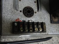
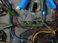
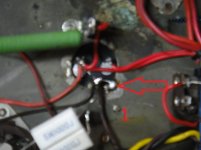
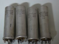
I'm revamping my tube monoblock power amplifier and I found this concern: the electrolytics capacitors (4 of them) are aluminium mount base (25+25, 500v). So, all of them are connected to chassis, no star ground. Each point at the base of the capacitor is connected to chassis and there is a wire to connect each one (-). As my new capacitors are JJ mount base, but plastic, should I create a star ground and disconnect each capacitor from chassis at it's base? Or continue to connect each one (-) to chassis?
It's a Mullard 5-20 PA type.
Any information is welcome ....
Last edited:
Is the rest of the amp a buss ground? For a star ground you most likely would have to redo all the grounding in the amp.
I think what I did on my 5-20 builds was use a buss ground but all the decoupling caps were grounded to the buss at their respective circuit keeping ground loops to a minimum, they turned out dead quiet even w/ 100db/1W/1M speakers.
I think what I did on my 5-20 builds was use a buss ground but all the decoupling caps were grounded to the buss at their respective circuit keeping ground loops to a minimum, they turned out dead quiet even w/ 100db/1W/1M speakers.
Thank you famousmockingbird for your replay.
No, there isn't a buss ground. Each stage has it's components connected to local chassis or to electrolytic capacitor.
I'm think do what you did: "on my 5-20 builds was use a buss ground but all the decoupling caps were grounded to the buss at their respective circuit keeping ground loops to a minimum".
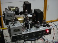
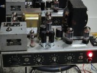
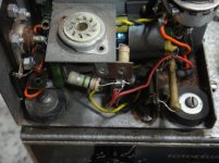
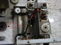
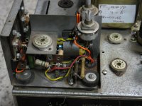
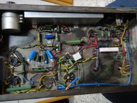
The monoblocks look and work good, but with some audible hum with no loads. Some pictures of the old ladies.
No, there isn't a buss ground. Each stage has it's components connected to local chassis or to electrolytic capacitor.
I'm think do what you did: "on my 5-20 builds was use a buss ground but all the decoupling caps were grounded to the buss at their respective circuit keeping ground loops to a minimum".
The monoblocks look and work good, but with some audible hum with no loads. Some pictures of the old ladies.
Attachments
Last edited:
Hi,
I'm revamping my tube monoblock power amplifier and I found this concern: the electrolytics capacitors (4 of them) are aluminium mount base (25+25, 500v). So, all of them are connected to chassis, no star ground. Each point at the base of the capacitor is connected to chassis and there is a wire to connect each one (-). As my new capacitors are JJ mount base, but plastic, should I create a star ground and disconnect each capacitor from chassis at it's base? Or continue to connect each one (-) to chassis?
Each cap should be isolated from the chassis, and the ground terminal of each cap should go to the chassis-connected star ground.
Each cap should be isolated from the chassis, and the ground terminal of each cap should go to the chassis-connected star ground.
Yes, that´s what I'm thinking to do. I will disassembly everything. The wires are not good and some coupling capacitors are out of tolerance. It will be a long term journey. I will replace almost every component including valves sockets. But I think it will worth at the end.
Yes, that´s what I'm thinking to do. I will disassembly everything. The wires are not good and some coupling capacitors are out of tolerance. It will be a long term journey. I will replace almost every component including valves sockets. But I think it will worth at the end.
You'll learn a lot, too. Use #20 solid copper wire and 63/37 solder, and much patience. Good luck.
If at all possible do not simply connect the -ve of the caps to the signal ground. Connect the reservoir -ve to the transformer CT (removing the CT from chassis if necessary). Then reservoir -ve to smoother -ve. Then smoother -ve to signal ground. This keeps charging currents well away from the signal ground.
Always think about where the currents go.
Always think about where the currents go.
If at all possible do not simply connect the -ve of the caps to the signal ground. Connect the reservoir -ve to the transformer CT (removing the CT from chassis if necessary). Then reservoir -ve to smoother -ve. Then smoother -ve to signal ground. This keeps charging currents well away from the signal ground. Always think about where the currents go.
Yes, this is much better than the usual single "star" grounding.
That's called "daisy chain" or so, this can reduce the hum and ground issues quite well just re-distibuting the capacitors along the power supply and avoiding ground currents in the most sensitive placesIf at all possible do not simply connect the -ve of the caps to the signal ground. Connect the reservoir -ve to the transformer CT (removing the CT from chassis if necessary). Then reservoir -ve to smoother -ve. Then smoother -ve to signal ground. This keeps charging currents well away from the signal ground.
Always think about where the currents go.
That's called "daisy chain" or so, this can reduce the hum and ground issues quite well just re-distibuting the capacitors along the power supply and avoiding ground currents in the most sensitive places
A daisy chain is different, it's just connecting parts in a line like links in a chain. Here, we're saying that each circuit subsection should have a "local" common, and then the several circuit commons should separately go to the main ground, which is usually the common point of the main filter capacitors. This common point then connects to the chassis. This should be the only place that any part of the circuit is connected to the chassis.
Some pictures
Thank you gentlemens ...
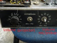
This is a modified Mullard 5-20 to work as PA. The modifications that I need to do might look intimidating at first, but are actually suprisingly easy to accomplish, since I have two monoblocks in working condition. The layout is almost the same I found for PA tube amplifiers on the web. The good news for me is that most of what I need is already there; the only problem were OTs, since they were rated at 800 ohms at outuput. I'm using a spare OT with 5k, 4/8/16 ohms (no ultralinear tap) 75 watts.
This work will consists of the removal of some stuff, de-soldering of wires and resistors from tube sockets and the like, and adding in the new connections in the right places. The chassis will be repainted.
I expect that the results turn out to be quite good, but this of course depends on your help, since I'm just a hobbyst; The operational condition at this time is good, considering the old components, wire and the ground issues I found. However, a lot of how well things turn out will depends on the choices I make in installing the modifications. There's ample room for experimentation. Maybe I will include a choke and, of course, come up with the golden arrangement of circuit stages and connections.
I'm very excited because I believe this all can be quite a learning experience.
The photos show some part's of this PA. I already sent an order to Tubedepot and Mouser. I expect they will arrives in two weeks (or more).
At this moment, I'm drawing the schematic from the circuit. Then, I will make a ground plan and I will need your help, since you guys are very expert.
Thank you gentlemens ...
This is a modified Mullard 5-20 to work as PA. The modifications that I need to do might look intimidating at first, but are actually suprisingly easy to accomplish, since I have two monoblocks in working condition. The layout is almost the same I found for PA tube amplifiers on the web. The good news for me is that most of what I need is already there; the only problem were OTs, since they were rated at 800 ohms at outuput. I'm using a spare OT with 5k, 4/8/16 ohms (no ultralinear tap) 75 watts.
This work will consists of the removal of some stuff, de-soldering of wires and resistors from tube sockets and the like, and adding in the new connections in the right places. The chassis will be repainted.
I expect that the results turn out to be quite good, but this of course depends on your help, since I'm just a hobbyst; The operational condition at this time is good, considering the old components, wire and the ground issues I found. However, a lot of how well things turn out will depends on the choices I make in installing the modifications. There's ample room for experimentation. Maybe I will include a choke and, of course, come up with the golden arrangement of circuit stages and connections.
I'm very excited because I believe this all can be quite a learning experience.
The photos show some part's of this PA. I already sent an order to Tubedepot and Mouser. I expect they will arrives in two weeks (or more).
At this moment, I'm drawing the schematic from the circuit. Then, I will make a ground plan and I will need your help, since you guys are very expert.
Attachments
-
 DSC01546.JPG247.2 KB · Views: 52
 -
 DSC01544.JPG652.3 KB · Views: 53
 -
 DSC01543.JPG292.1 KB · Views: 52
 -
 DSC01541.JPG615.7 KB · Views: 71
 -
 DSC01538.JPG715.9 KB · Views: 76
 -
 DSC01537.JPG727.2 KB · Views: 84
 -
 DSC01535.JPG98.6 KB · Views: 89
 -
 DSC01534.JPG788.7 KB · Views: 85
 -
 DSC01533.JPG272.2 KB · Views: 87
 -
 DSC01547.JPG712.2 KB · Views: 59
- Status
- Not open for further replies.
- Home
- Amplifiers
- Tubes / Valves
- Revamping Tube Amp Monoblock - capacitor grounding concern