Last yeat I decided to buy a M&A TVA-1 on EBay. It was a modified one, with KT-90 tubes and other changes. When I received it I had the bad surprise that it was humming and buzzing, so I decided to revamp it.
It took a few months, but the result was beyond my expectations. I restored the KT-88 tubes and the original schematic, but understood a few things and made a few changes which could be of help to others.
I am new to this Forum, I searched it for similar topics but found none.
I ask for a bit of advise: is it worth that I occupy a few magabytes of space on this Forum to present what I did?
I have a short narrative, plus some schematic diagrams, component list and photos: how many megabytes can I use for posting them?
Thank you
Giovanni
TVA-1 revamping
I have been requested by a few members to post about the revamping of my TVA-1 (which I did in 2009 - time is fast...), which is still working very well, so I attach the narrative and a few photos.
I am available to provide additional photos and/or information / clarifications if necessary.
Giovanni
Attachments
-
TVA-1 revamping article.pdf32.1 KB · Views: 762
-
Measurements.pdf8.3 KB · Views: 408
-
Component list.pdf10.3 KB · Views: 458
-
 13 - internal view.jpg84.6 KB · Views: 1,174
 -
 03 - As purchased - inside.jpg107.9 KB · Views: 1,062
 -
 01 - As purchased front.jpg54.5 KB · Views: 1,129
 -
 09 - Main board.jpg119.9 KB · Views: 1,042
 -
 10 - Main board.jpg94.4 KB · Views: 990
 -
 11 - Bias power board.jpg116.9 KB · Views: 563
 -
 16 - TVA-1 front.jpg118.7 KB · Views: 563
Thank you!
Hello Giovanni,
First of all thank you for the TVA-1, Mentmore pictures and your precise description of the changes you did make after receiving the amplifier.
As I own one erly version of the TVA-1(before sold to Mentmore) which was received with major changes in bias as well as ground wiring, I got the same hum problems described by you.
The only thing I really would like to know :
Where did Anthony Michaelson and Kevin Austin originally make the chassis ground ? The TVA-1 has a 2 mm thick polished steel chassis . Did the two gentlemen make the ground close the the RCA connectors on the rear panel, or close to the large PSU capacitors?
Do you have a schematic of the ground wiring from your Mentmore 100, Ind.?
Really appreciate your help on this.
Best regards
Gudmund
I have been requested by a few members to post about the revamping of my TVA-1 (which I did in 2009 - time is fast...), which is still working very well, so I attach the narrative and a few photos.
I am available to provide additional photos and/or information / clarifications if necessary.
Giovanni
Forgot to say that some secrets of the older TVA-1 is visible on TUBEAMP
Could you explain the function of the little relay circuit on the pictures? is it high volt delay?
rgds
Hello Gudmund,
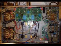
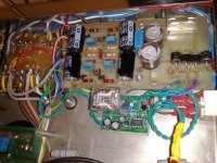
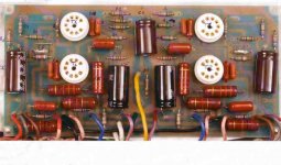
the chassis ground connection is on the power transformer, where the Earth connection from the 220V socket is connected to the central pole of the transformer (you can see it from the first picture, in the low left corner).
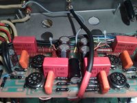
The little relay circuit is to apply the High Voltage with a delay (about 30 sec.) vs. the bias and filaments heating. In the final version I added 2 resistors (see the picture attached) such that the HV is gradually increasing, so to treat even more gently the tubes. I put 6k8 resistors, a better value is a bit lower, say 4k8.
I don't have an M-100, so I cannot articulate on this.
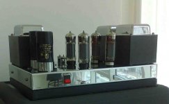
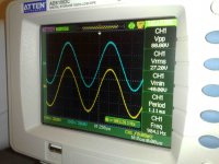
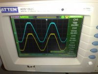
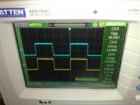
Finally, I take the opportunity to post a few more pictures, including some oscillograms which show the max. power and the clipping.
Giovanni
the chassis ground connection is on the power transformer, where the Earth connection from the 220V socket is connected to the central pole of the transformer (you can see it from the first picture, in the low left corner).
The little relay circuit is to apply the High Voltage with a delay (about 30 sec.) vs. the bias and filaments heating. In the final version I added 2 resistors (see the picture attached) such that the HV is gradually increasing, so to treat even more gently the tubes. I put 6k8 resistors, a better value is a bit lower, say 4k8.
I don't have an M-100, so I cannot articulate on this.
Finally, I take the opportunity to post a few more pictures, including some oscillograms which show the max. power and the clipping.
Giovanni
Attachments
-
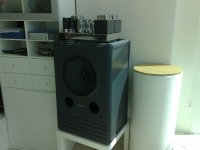 TVA-1 on Tannoy.jpg545 KB · Views: 403
 -
 Soft start resistors.jpg899.5 KB · Views: 388
 -
 04092009824.jpg611.2 KB · Views: 483
 -
 Main board with component numbers.jpg58.8 KB · Views: 468
 -
 Schematic - Revamped.jpg60.6 KB · Views: 843
 -
 BiasChart-KT88.jpg33.9 KB · Views: 693
 -
 18 - oscillogram.jpg147.3 KB · Views: 393
 -
 19 - oscillogram (clipping).jpg137 KB · Views: 251
 -
 20 - oscillogram (square wave).jpg159.6 KB · Views: 254
Hello Gudmund,
the chassis ground connection is on the power transformer, where the Earth connection from the 220V socket is connected to the central pole of the transformer (you can see it from the first picture, in the low left corner).
The little relay circuit is to apply the High Voltage with a delay (about 30 sec.) vs. the bias and filaments heating. In the final version I added 2 resistors (see the picture attached) such that the HV is gradually increasing, so to treat even more gently the tubes. I put 6k8 resistors, a better value is a bit lower, say 4k8.
I don't have an M-100, so I cannot articulate on this.
Finally, I take the opportunity to post a few more pictures, including some oscillograms which show the max. power and the clipping.
Giovanni
Hi Giovanni,
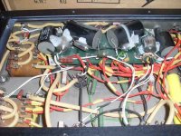
Yes - it's possible to see the black wire connected to the zero voltage central point between the two 190Vac tags on the powertransformer . This is the erth connection for the incomming AC...which could be 220Vac ....depending on the countrys local AC supply.
It's the signal chassis point I am looking for...after the two 1000uF/400V caps ....and the ground wire from the driverboard. Where are these two wires connected to the steel chassis on your valveamp? Normally the chassis do only have one central connection for all internal ground wiring....the amplifier do not have floating ground..or?
All my DIY amplifiers has a central ground point, where the RCA screen connectors ,zero voltage wires from PSU caps and ground wires from the driver board mets in one point only (starpoint). I think the TVA-1 is made the same way?
Gudmund
Gudmund,
I don't remember having seen these grounding connection anywhere, I looked at all the pictures I have and there is no sign of such connection.
The next time I open the amp I'll search for it.
Giovanni
I don't remember having seen these grounding connection anywhere, I looked at all the pictures I have and there is no sign of such connection.
The next time I open the amp I'll search for it.
Giovanni
Gudmund,
I don't remember having seen these grounding connection anywhere, I looked at all the pictures I have and there is no sign of such connection.
The next time I open the amp I'll search for it.
Giovanni
Thanks Giovanni,
You have been a great help so far...if you could find the chassis ground when its time for service, I would appreciate that very much.
Gudmund
TVA-1 , Mentmore Curiosity
As TVA-1 owner you might like to know what has been written:
"I spoke with a man named Colin in UK. He was the UK distibutor of
Papworth amplifiers.
I was informed that Tim de Paravicini was designing for Anthony Michaelson and
Kevin Austin at that moment, and that the TVA-1 and TVA-10(may be also the
Mentmore M100) was more or less Tim's amplifiers....hence TVA-1 = Tim's Valve
Amp - the first.
Michaelson and Austin went broke, and Anthony Michaelson went on to found
Musical Fidelity , where the M & A designs were sold to Mentmore.
Colin was not sure that the Mentmore M100 is designed by Tim de Paravicini, but
I have a copy of the original M100 drawing, and the circuit looks pretty much
like a TdP design to me?"
Tim's Valve Amp ....TVA-1
I don't have an M-100, so I cannot articulate on this.
Giovanni
As TVA-1 owner you might like to know what has been written:
"I spoke with a man named Colin in UK. He was the UK distibutor of
Papworth amplifiers.
I was informed that Tim de Paravicini was designing for Anthony Michaelson and
Kevin Austin at that moment, and that the TVA-1 and TVA-10(may be also the
Mentmore M100) was more or less Tim's amplifiers....hence TVA-1 = Tim's Valve
Amp - the first.
Michaelson and Austin went broke, and Anthony Michaelson went on to found
Musical Fidelity , where the M & A designs were sold to Mentmore.
Colin was not sure that the Mentmore M100 is designed by Tim de Paravicini, but
I have a copy of the original M100 drawing, and the circuit looks pretty much
like a TdP design to me?"
Tim's Valve Amp ....TVA-1
The original text
The original text about Papworth from UK:
Papworth M100 Power Amps
As TVA-1 owner you might like to know what has been written:
Tim's Valve Amp ....TVA-1
The original text about Papworth from UK:
Papworth M100 Power Amps
Hello. I stand, I'm John. Please, I need help. I have a M100 Mentmore stages. That Deplete the EL34 in a few hours. I can facilitate the scheme PSU, BIAS settings, and valve manufacturer recommended.
A greeting and thanks.
A greeting and thanks.
Gudmund,
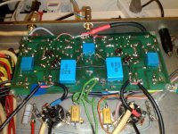
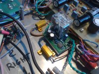
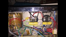
I finally re-open my TVA-1 for a bias checking (all ok after 6 years of moderate use) and to replace the big filter capacitors with bigger ones (2200 uF each instead of 1000 uF), so I took the opportunity to take a picture of the chassis ground connection (posted here below), which is the yellow-green cable and is as per the schematic diagram. Hope this helps.
Giovanni
Attachments
- Status
- Not open for further replies.
- Home
- Amplifiers
- Tubes / Valves
- Revamping of a Michaelson & Austin TVA-1