Using RETRO with Ortofon 2M Red.
Hi Russ,
I am planning to use the circuit posted on #21 with my Ortofon 2M Red MM cartridge (2M Red). The recommended load resistance is: 47K and the recommended load capacitance is 150-300 pF. What all components should be modified in the original schematic for making it suitable for that cartridge ? Please advice.
Best regards,
Bins.
Hi Russ,
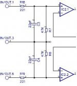
I am planning to use the circuit posted on #21 with my Ortofon 2M Red MM cartridge . The recommended load resistance is: 47K and the recommended load capacitance is 150-300 pF.
Load is already 47k, R7 & R8. Caps C3 & C4 are 22pF, change them to 150-300pF.
")
Edit: I see the schema in post #21 does not show those resistors, they would be parallel with c3 & c4 which are after the 100R input resistors.
Attachments
Last edited:
Remember that the capacitive loading the cartridge sees consists of ALL capacitances: capacitance in the tonearm wires, capacitance in the cable from tonearm to preamp, input capacitance in any preamp wiring between chassis jack and PCB, any specific capacitor across the preamp input.
Something I didn't notice before. The schematic attached to post 55 (Hi-Z MM version) actually loads the cartridge with 94K Ohms (from IN/OUT.1 to IN/OUT.6), not 47K Ohms. More precisely, 94K + 442 Ohms. This should be fixed...
Back to the capacitance. Before picking a loading cap to put on the PCB, you need to know the capacitance of the other portions of the system. If you're lucky, the maker of your tonearm will tell you the values of capacitance in the tonearm and/or interconnect. If not, you need to measure them.
MC cartridges are much lower impedance so the capacitive loading is less of an issue, but MMs are more critical.
Note also that whatever value you decide you need on the PCB, the values for C3 and C4 need to be double that because they are in series.
The one with the ruby cantilever? We had this one running in our ETF setup (stripped and mounted in a wooden body). Very nice cartridge.Soundsmith retipped Denon DL-103 LOMC
Hi Russ,
I would be interested in a Retro to use with my Soundsmith retipped Denon DL-103 LOMC. I think I sent a pm but the site may have logged me out first. LMK Thanks, Jeff
Excellent!
i just got back from a trip, so I am trying to catch up with email etc.
We should have the circuit available for people to try soon.
Cheers!
Russ
Hi Brian,
Are the op-amps that have been chosen for the final Hi-Z kit the same as Russ' choices in post 69? I ask because I think a FET-input op-amp for IC2 (such as the OPA1642) with much lower input current noise would better suit my MM cartridge which has high source impedance.
Thanks!
Are the op-amps that have been chosen for the final Hi-Z kit the same as Russ' choices in post 69? I ask because I think a FET-input op-amp for IC2 (such as the OPA1642) with much lower input current noise would better suit my MM cartridge which has high source impedance.
Thanks!
Not the Brian you were expecting, but...
Analyzing phono preamp noise for MM cartridges is not easy. The source impedance of an MM cartridge is not a single number -- it varies with frequency. One of the old National Semi. audio applications books (late 1970's ?) had a good ap-note on the topic, if you can find it. It definitely considered the varying cartridge source impedance, but I don't recall if it dealt with both voltage and current noise on the op-amp. You also need to consider the phase of the impedance at various frequencies, not just the magnitude.
That said, you make a good point about using a JFET input amp. However, comparing OPA1642 against OPA1611 and you see that the voltage noise on the OPA1642 is 5.1 nV/rt(Hz) typ. at 1 kHz which is substantially higher than the OPA1611. So all this would take a spreadsheet to derive an answer, but do-able.
Then... given the final noise vs. frequency, you need to consider the ear's varying sensitivity to sound at these different frequencies -- A-weighting curve or whatever.
Then there's 1/f noise to consider on the FET vs bipolar -- different 1/f corners will affect LF noise.
On a number of occasions, I've toyed with the idea of using a number of low-noise FET-input amps (OPA627, OPA1642, whatever...) in parallel with their outputs combined by a summing amp. For example, eight OPA1642 in parallel would get the voltage noise down to about the level of the OPA1611 with vanishingly low current noise.
BTW, it might be worth reading Douglas Self's new book on small signal audio design that has just been published.
Last edited:
R.I.P. ????????????????
Regards Gerhard
Only my spare time. We have a lot going on, and only so many hours in the day (and dollars in the bank).
- Home
- More Vendors...
- Twisted Pear
- Retro - A fully symetrical phono stage with RIAA filter