Hi,
we (I) would like to know whether you plan 2, or 4, or 8 caps in this two channel amplifier? It will/should make a difference to our advice.Tom,
is that two 47mF per rail, or per channel, or per stereo amp?
Shawn,
Like I said before ....put a soft start in it. I have failed in the past to listen to DJK's advice and it has bit me in the *** many times.
I'm not going to debate that it will or won't happen sooner or later because it has and will. I have repaired 1000's of amps in the past and I'm not ashamed to tell anyone that I have been schooled in the past by Mr. DJK.
I have an assortment of blown bridges in the 25 and 35A variety. I have melted switches and an assortment of Triacs.
There is no more need for discussion on it. It will happen period.
Shawn, put an inrush limiter in and a soft start and I guarantee it will function without a problem.
I'm not an engineer either but have many years of fixing what others haven't designed correctly.
Hi,
were these caused by the lack of a soft start or some other cause? Please enlarge.I have an assortment of blown bridges in the 25 and 35A variety. I have melted switches and an assortment of Triacs.
Nobody is claiming that rectifiers cannot blow up or that it is not theoretically possible for this to be due to the lack of a soft start when charging a large bank of caps. It's still never happened to me over many years. I have seen several spectacular blow ups caused by faulty soft start circuitry on the mains side....even holes blown through 19" rack cases
Here endeth my input on the subject....I've got better things to do.
Here endeth my input on the subject....I've got better things to do.
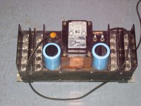
2 caps
With the existing set up only two caps can be used in total. Look how they mount.
Cheers,
Shawn.
AndrewT said:Hi,
we (I) would like to know whether you plan 2, or 4, or 8 caps in this two channel amplifier? It will/should make a difference to our advice.
With the existing set up only two caps can be used in total. Look how they mount.
Cheers,
Shawn.
Attachments
I have neither the time or patience to debate this with you Andrew T. We can go back and forth with this mine is bigger than yours attitude but I'm not going to do so.
Shawn, You have my recommendations based on years of repair of both commercial and home equipment. The choice is yours.
Shawn, You have my recommendations based on years of repair of both commercial and home equipment. The choice is yours.
burnedfingers said:I have neither the time or patience to debate this with you Andrew T. We can go back and forth with this mine is bigger than yours attitude but I'm not going to do so.
Shawn, You have my recommendations based on years of repair of both commercial and home equipment. The choice is yours.
I would be surprised if there is no way to calculate the amount of load a particular uncharged cap bank places on its rectifier and transformer? It's not that I can't be bothered to look it up, I simply don't have the time but I'd like to.
Also, it would be nice to measure such a demand it in real time? If some one knows a method using VOM's or a scope I could try it? It is a fair debate this topic, but no one has put their money where their mouth is. I admire T's scientific approach to amps and power supplies but I am also a great fan of real world experiences from the bench.
I'd like to see the math and do the measurements! Is it that hard to figure out? I'll have those caps in the chassis by the end of next week. 😉
Cheers,
Shawn.
The world according to Quasi ....again.
The issue for soft start for me is not to protect the 35A bridge, I doubt you could fit enough capacity (capacitance?) in the crown to exceed the peak current capability of a 35A bridge anyway.
For me using a soft-start does two things;
- stops that annoying fuse replacement programme
- allows the correct fuse that will offer quick protection, rather than some overated slow blow thing.
Cheers
Q
Hi Tom,
you plan to fit just +-47mF supplied from a single rectifier.
This is peanuts. (I would go MUCH bigger, but you already know where I come from).
Soft start to delay or slow down capacitor charging is unlikely to be required, but in any case, I have already pointed you to a better way of achieving slow charge up.
Soft start for your EI should be similar to what Crown originally fitted. It works, so why change it. There is a senario for which I would change it. Do you want me to elaborate?
Have you tried inputting data into PSUD2?
It will let you examine the start up and longer term currents that pulse or flow through the various components around the transformer.
Burned fingers,
You misunderstand my argument.
I am very much in favour of soft start, for exactly the reasons just listed by Quasi.
I plan to fit it to all my new amplifiers, even though I never suffer from dimming lights nor distribution board MCB cut outs.
But, I am passing on advice and information in response to an enquiry. I try to be objective and where subjective I generally say so.
Various experiences are being given, but I suspect some have been coloured by an alternative agenda.
Please confirm under what circumstances these rectifiers failed. I for one will be grateful for the knowledge and I suspect others would like to avoid the same pitfalls.
If these failures that have been listed are solely due to omission of a soft start then say so.
...you plan to fit just +-47mF supplied from a single rectifier.
This is peanuts. (I would go MUCH bigger, but you already know where I come from).
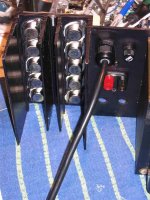
I know where you're coming from T but I have physical restrictions due to the chassis.
Of course and anyone else that has a circuit that will fit in this enclosure. Real-estate is a serious issue so please look at the chassis in the picture before recommendations that include chunky relays and transformers.There is a senario for which I would change it. Do you want me to elaborate?
Have you tried inputting data into PSUD2?
It will let you examine the start up and longer term currents that pulse or flow through the various components around the transformer.
I only tried one program like this before and it was unintuitive and awkward at best. I will look in to the PSUD2.
Thanks,
Shawn.
Hi Tom,
I think you will find PSUD2 very easy to set up and fairly simple to interpret the results.
But as usual, the Forum is here (hear) to help.
The change I would make is to ensure that the delay in the soft start is set appropriately to suit establishing flux in the transformer (about 200mS to 300mS) and not to use the resistive dropper to slow down the charging into the smoothing caps.
Secondly, I would look at Thermistor limiting in the transformer secondary, again with a relay to switch to full voltage after a suitable delay, 5S to 10S depending on amplifier requirements.
The relays in both circuits are open at switch on.
The soft start circuit relay closes after the main flux pulse has passed. Similarly the slow charge relay closes after the caps have substantially charged and voltage either side of the contacts should be within a volt or two.
A closing relay suffers less damage than an opening relay.
On that basis the relays in both locations can be low duty and AC rated. The control board for each should be capable of being designed to be compact even with the relay on board, although I would place the soft start relay OFF board due to the mains voltage that it carries.
Hi Shawn,
Good luck for you then!
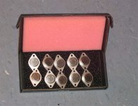
I normally want different date codes to see how consistant the process is. But then again, I normally use these in prototypes. There are times when I purposly mismatch outputs and drivers to see what the design will tolerate. Same for input pairs. I typically get what I expect.
-Chris
Good luck for you then!
I normally want different date codes to see how consistant the process is. But then again, I normally use these in prototypes. There are times when I purposly mismatch outputs and drivers to see what the design will tolerate. Same for input pairs. I typically get what I expect.
-Chris
anatech said:Hi Shawn,
Good luck for you then!
I normally want different date codes to see how consistant the process is. But then again, I normally use these in prototypes. There are times when I purposly mismatch outputs and drivers to see what the design will tolerate. Same for input pairs. I typically get what I expect.
-Chris
I was talking Crown amp talk yesterday, a person near by the conversation chimmed in that I should contact Micron! You're old Micron. What a hoot. Apparently you come highly recommended in Toronto by PA Tech guys. How is Micron these days?
Good on you.
Shawn.
Hi Shawn,
I sold Micron about 9 years ago. I haven't keep up with them, so I don't know what they are up to. The best guys left a while ago as well. Their brand of business was very different to mine. The sale did not conclude nicely either.
I have had many old customers hunt me down to do some work for them. That's a nice feeling.
-Chris
AndrewT said:Hi Tom,
But as usual, the Forum is here (hear) to help.
The change I would make is to ensure that the delay in the soft start is set appropriately to suit establishing flux in the transformer (about 200mS to 300mS) and not to use the resistive dropper to slow down the charging into the smoothing caps.
Secondly, I would look at Thermistor limiting in the transformer secondary, again with a relay to switch to full voltage after a suitable delay, 5S to 10S depending on amplifier requirements.
A two stage approach! I'm not certain the old Sea Hag is worthy? 😀 Is there any demise using the traditional resistor in line trick?
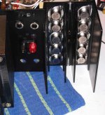
I'm mounting TO-3's...
Attachments
Re: I'm mounting TO-3's
Looks great, good luck!
TomWaits said:I could turn it on tonight? 😀
Shawn.
Looks great, good luck!
Tom,
remember to power it through the in line mains light bulb to minimise damage in event of some mis-wiring.
Good luck, no you don't need luck. May the force be with you.
remember to power it through the in line mains light bulb to minimise damage in event of some mis-wiring.
Good luck, no you don't need luck. May the force be with you.
Re: Re: I'm mounting TO-3's
I spoke to soon, the wiring is very plentiful. 🙁 I am going to try and tidy it a bit when I hook it all together but for now you can seen all of the leads are on the Driver board and now I'll get back to the chassis. This may take another evening or two?
I ordered heat shields to be made today. I think they will be the right size and I think they want $20 cash for 4 pieces but it is hard to tell because the two guys did not speak English and I don't speak Portuguese! 😀 It was fun and we'll see what they can cook up for me tomorrow when I go back to see them.
The heat shields slide into the heat sink over each bay of transistors providing mechanical protection while allowing the convection process to cool it. I have never seen them but I read about them in the service manual.
Cheers,
Shawn.
rdf said:
Looks great, good luck!
AndrewT said:Tom,... May the force be with you.
I spoke to soon, the wiring is very plentiful. 🙁 I am going to try and tidy it a bit when I hook it all together but for now you can seen all of the leads are on the Driver board and now I'll get back to the chassis. This may take another evening or two?
I ordered heat shields to be made today. I think they will be the right size and I think they want $20 cash for 4 pieces but it is hard to tell because the two guys did not speak English and I don't speak Portuguese! 😀 It was fun and we'll see what they can cook up for me tomorrow when I go back to see them.
The heat shields slide into the heat sink over each bay of transistors providing mechanical protection while allowing the convection process to cool it. I have never seen them but I read about them in the service manual.
Cheers,
Shawn.
Attachments

- Home
- Amplifiers
- Solid State
- Resurrecting a Crown DC300A