Hi,
I'm restoring an old 2N3055 based amp for sentimental reasons. I built it from a kit back in the eighties when my interest in electronics was growing. It never sounded as good as my Marantz amp and I later lent it to a cousin. It was used and abused on many parties for years and finally dumped. I took it back, replaced all the pots and electrolytes, rewired everything, placed connectors everywhere possible for easy accessibility, built a new power supply.
A knowledgeable friend of mine pointed that with the values of the resistors the amp was probably working in class B rather than AB. He was right, I measured, added bias trimmers and biased the output transistors. And it worked much better than ever. That is until I cut all surplus wires, twisted and packed all nicely and placed all modules back in the box. Left channels worked fine the right was humming slightly with very weak output signal. I started tapping elements and wires for loose contact when all of a sudden one of the original Motorola 2N3055 literary burned into flames with DC on output.
I had to replace half of the semiconductors (actually replaced all of them later). The new 2N3055 are ST. Now I have a new problem. First I couldn't bias the transistors enough and then, especially on cold start, they started overheating. A small 2.2uF in series with analogue voltmeter shows AC voltage, like something is oscillating. OK, I doubted that the biasing trimmer might be loosing contact and I replaced it. Now I could easily bias the quiescent current (20 mA), but it starts growing steadily until at one moment it goes wild, I get the AC on output and transistors are very heated. It is interesting that I provoke that state by always touching and checking the output transistors for heating.
I attach the schematics (I lost the original), the only difference being that the actual circuit has 4x2N3055 for 120W RMS per channel on 4Ohms. Any suggestions how to proceed and stabilize the circuit?
Attachments
Hi sharbatgula,
Your new ST 2N3055 is much faster than the old transistors were. You have to change the compensation capacitor for the new transistors (change both).
The action where you turn up the bias and suddenly get oscillation is very common in cases like this. Expected behavior, so relax. A faster op amp might be needed. What is in there right now? Also, lead dress (how the wires run) can cause this as well. Keep the output cables away from everything else, the input signal should also run away from everything, but especially the output wires.
So, several possible causes and you may have a combination of them. Do one thing at a time with this. Can you take a picture of how your amplifier goes together for us?
-Chris
I had exactly the same problem with an old Maplin 225WRMS amplifier module.
I bought it as faulty and with missing output transistors.
So I bought in new transistors and it oscillated very badly.
I had to change the VAS capacitor to a higher value to stop the oscillation.
I tested the new transistors on a semiconductor analyser and they had much more gain than in the datasheet for the original parts.
I had exactly the same problem with an old Maplin 225WRMS amplifier module.
I bought it as faulty and with missing output transistors.
So I bought in new transistors and it oscillated very badly.
I had to change the VAS capacitor to a higher value to stop the oscillation.
I tested the new transistors on a semiconductor analyser and they had much more gain than in the datasheet for the original parts.
Here is the schematic.
C8 is VAS capacitor.
An externally hosted image should be here but it was not working when we last tested it.
Last edited:
Faster transistors can only make the design more stable, not less stable.Hi sharbatgula,
Your new ST 2N3055 is much faster than the old transistors were. You have to change the compensation capacitor for the new transistors (change both).
Try replacing the electrolytic capacitor across TR4.
edit: Compensation capacitor (Cdom) value does seem fairly low however. Increasing the value will compromise distortion performance, I would try replacing all the old caps the same values before resorting to increasing Cdom.
Last edited:
Hi TMM,
How about not running to the soldering iron to change parts out? You can't find problems that way for starters, but you can create a pile of new issues. Both output transistors should be of the same type, as in manufacturer and version. The 2N3055 was first created as a regulator pass transistor with an F3 of 19 KHz. Yes, 19,000 Hz to prevent oscillation when the part was mounted off the PCB and on a heat sink. That part was originally only good for Vc-e of 60 VDC. Newer parts can handle 100 VDC and maybe a few MHz. So you see, today's 2N3055 has very little in common with the original part.
Increasing Cdom will not compromise the distortion as long as you have it in the right ball park. We aren't talking about a low distortion amplifier here to begin with. Of course, we could always have an amplifier that blows up with very low distortion! 🙂
Always consider the application when you apply something you have read. Often a statement has the unwritten "all other things considered equal". Once you change those conditions (as in this case), you can't blindly apply something from a different situation. THD is pretty high when the thing is oscillating.
-Chris
Not when they are output transistors in a circuit designed for much slower parts!Faster transistors can only make the design more stable, not less stable.
How about not running to the soldering iron to change parts out? You can't find problems that way for starters, but you can create a pile of new issues. Both output transistors should be of the same type, as in manufacturer and version. The 2N3055 was first created as a regulator pass transistor with an F3 of 19 KHz. Yes, 19,000 Hz to prevent oscillation when the part was mounted off the PCB and on a heat sink. That part was originally only good for Vc-e of 60 VDC. Newer parts can handle 100 VDC and maybe a few MHz. So you see, today's 2N3055 has very little in common with the original part.
Increasing Cdom will not compromise the distortion as long as you have it in the right ball park. We aren't talking about a low distortion amplifier here to begin with. Of course, we could always have an amplifier that blows up with very low distortion! 🙂
Always consider the application when you apply something you have read. Often a statement has the unwritten "all other things considered equal". Once you change those conditions (as in this case), you can't blindly apply something from a different situation. THD is pretty high when the thing is oscillating.
-Chris
That's not how it works. Cdom rolls off the open-loop gain of the system so the open loop gain reaches unity before the open-loop phase response reaches 180degrees and therefore causes positive feedback, i.e. self oscillation.Hi TMM,
Not when they are output transistors in a circuit designed for much slower parts!
How about not running to the soldering iron to change parts out? You can't find problems that way for starters, but you can create a pile of new issues. Both output transistors should be of the same type, as in manufacturer and version. The 2N3055 was first created as a regulator pass transistor with an F3 of 19 KHz. Yes, 19,000 Hz to prevent oscillation when the part was mounted off the PCB and on a heat sink. That part was originally only good for Vc-e of 60 VDC. Newer parts can handle 100 VDC and maybe a few MHz. So you see, today's 2N3055 has very little in common with the original part.
Increasing Cdom will not compromise the distortion as long as you have it in the right ball park. We aren't talking about a low distortion amplifier here to begin with. Of course, we could always have an amplifier that blows up with very low distortion! 🙂
Always consider the application when you apply something you have read. Often a statement has the unwritten "all other things considered equal". Once you change those conditions (as in this case), you can't blindly apply something from a different situation. THD is pretty high when the thing is oscillating.
-Chris
The open loop phase depends directly on the transition speed (Ft) of the transistors. Using transistors that are slow as snails will cause the open loop phase response to reach 180deg at a lower frequency, therefore requiring a larger Cdom to get the open loop gain to unity before that frequency. To 'design for slow parts' would mean to increase Cdom. Where you encounter problems is using slow transistors in a circuit designed for fast transistors, not the other way around. It is true that also the gain/Hfe of newer transistors is higher, however the gain of the output stage is still ~unity due to local feedback. Even if the VAS transistor was replaced with a fast part with higher gain, usually the increase in Ft is enough to offset the increase in gain.
The amount of open loop gain is directly related to how much you can linearise the amplifier through the use of negative feedback. All things otherwise the same, an amplifier with 100dB open loop gain will be more linear than one with only 60dB.
For most designs, open loop gain is already starting to roll in the 100-1KHz range. Increasing Cdom will start the roll off at yet a lower frequency, compromising distortion at every frequency above the rolloff point.
You make a valid point that a low distortion amp that doesn't work isn't very useful. I'm just skeptical that the stability of the original design was so marginal that even touching the output transistors with a finger would be enough to push it over the edge.
It is also worth noting that the amount of bias through the output transistors can affect the Ft of the output devices, and therefore push it over the edge of stability. The designer may have never intended the amplifier to run at the bias current that the OP is using. In that case, increasing Cdom is appropriate.
Last edited:
Hi TMM,
Yes, Cdom does reduce feedback as frequency goes up, but it also lowers the impedance of the stage as the circuit transitions over.
Absolutely correct about the slower outputs, but the circuit was designed with those and made (possibly) marginally stable. But you would expect to see bursts of oscillation if the amp was running at zero bias current, or very, very low current. So the designers would have had a problem even after they turn the bias down. They didn't care? Very possible.
I will agree that the higher amount of feedback you have as the frequency goes up will give you lower distortion. But there is nothing linear about the 2N3055 and its beta curve vs current. This amplifier probably did not meet it's distortion spec to begin with. That is why worrying about this design isn't reasonable. It's cheap and cheerful, sounds decent probably. Would have survived frat parties most likely. The perfect beginners amplifier.
If we were talking about a Blameless amplifier, or anything else that was well designed and well made, I would be right there with you. But this amplifier might not deliver the goods. Besides, we don't even know what op amp is used as the front end. Could be a 4558, or maybe a 741. An NE5534 would change things, as would an LM318 or TL072. Too many unknowns to make a firm judgement.
The diagram in post #5 is not this amplifier, the link in post #1 is what we are talking about.
-Chris
I thought the OP's amplifier was the one in post #5, my bad.
You are right that it's hard to draw any conclusions about stability without knowing which IC is used. OP should probably place a small capacitor across R4, say 22pF or so and increase until stability is achieved.
You are right that it's hard to draw any conclusions about stability without knowing which IC is used. OP should probably place a small capacitor across R4, say 22pF or so and increase until stability is achieved.
Probably best to still replace the cap across T4 if it is an old electrolytic. Failing that there doesn't seem to be anything that could go wrong with the circuit if it worked originally. Cdom is internal to the opamp in this design. Placing a capacitor across R4 provides additional compensation.
Another area to look at is Q10, the quasi complementary output does have a habbit of oscillating.
There are a couple of ways of addressing this:
- A smallish capacitor, 220pF, between the base and collector of T8
- A base "stopper" resistor of 100 ohms or so on t8, a few ohms on T10
Good luck!
There are a couple of ways of addressing this:
- A smallish capacitor, 220pF, between the base and collector of T8
- A base "stopper" resistor of 100 ohms or so on t8, a few ohms on T10
Good luck!
Wow! I didn't expect so much and so fast response. Thank you guys.
@Anatech
- The opamap is TL081, which is also new ST make, but I had the same problem with the original TL081.
- Unfortunately the output transistors are off the PCB, they always were. I just rewired and twisted the BCE wires of each transistor and harnessed with a heat shrinking conduit
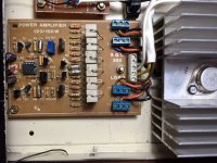
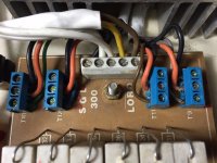
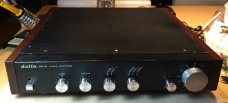
- I attach additional pictures showing details of how the PCB and heat-sinks arranged. The last picture just to show what it looks after years of abuse. I still think it has an attractive retro look worth an attempt to restore it.
@TMM
- The capacitor across T4 is 3.3 nF not electrolytic so I didn't replaced that one.
The pdf that I attached in my first post is multi page and holds values for all parts on page 2.
So, based on the additional information, what are your suggestions:
- replace with faster opamp?
- try with compensation capacitors on T4 or T8 or maybe change the value of C3?
Thank you guys!
@Anatech
- The opamap is TL081, which is also new ST make, but I had the same problem with the original TL081.
- Unfortunately the output transistors are off the PCB, they always were. I just rewired and twisted the BCE wires of each transistor and harnessed with a heat shrinking conduit
- I attach additional pictures showing details of how the PCB and heat-sinks arranged. The last picture just to show what it looks after years of abuse. I still think it has an attractive retro look worth an attempt to restore it.
@TMM
- The capacitor across T4 is 3.3 nF not electrolytic so I didn't replaced that one.
The pdf that I attached in my first post is multi page and holds values for all parts on page 2.
So, based on the additional information, what are your suggestions:
- replace with faster opamp?
- try with compensation capacitors on T4 or T8 or maybe change the value of C3?
Thank you guys!
Attachments

Last edited:
P.S.
The original 2N3055 from the eighties burned after doing only the following changes:
- rewiring of output transistors
- biasing them.
It worked fine for a couple of hours outside that metal box. When placed in the box I additionally trimmed the output transistor's wires.
After it blew I replaced with new ST 2N3055 and from there it became worse
So it could be the twisting of the wires or ground coupling (the wires are close to the metal box)
Are the 2N3055 well isolated from the heatsinks ? some of the mounting screws seem to have insulators, others not ?
Yes they are. The other insulator ring is placed from the bottom side with same effect. I use the screw head to establish contact with the collector from above but isolate it from the heat-sink from below where I also connect the collector with a ring like washer/connector.Are the 2N3055 well isolated from the heatsinks ? some of the mounting screws seem to have insulators, others not ?
I will check the quality of the screw had connection to the body of the 2N3055.
Last edited:
Hi Sharbatgula,
A possible cause may be the wiring especially the ground wiring. I assume you have follow the star point ground. After rewiring perhaps you have connected a wire in the wrong place. Did you include a coil and an RC filter network at the output of the amplifier?
A possible cause may be the wiring especially the ground wiring. I assume you have follow the star point ground. After rewiring perhaps you have connected a wire in the wrong place. Did you include a coil and an RC filter network at the output of the amplifier?
Tried the 220 pF across base and collector of T8 and it seemed to tame the oscillations. But I measured only 5 mA quiescent current. I tried to increase with only a couple of turns of the trim pot but there was no change. I left the amp on for about 10 minutes to check the current again. Unfortunately, after a while R21 burst into fire. T3, T7, and all four 2N3055 are burned.
I'm really disappointed, not so much from the outcome but from not understanding what's going on.
I'm really disappointed, not so much from the outcome but from not understanding what's going on.
Hi Sharbatgula,
A possible cause may be the wiring especially the ground wiring. I assume you have follow the star point ground. After rewiring perhaps you have connected a wire in the wrong place. Did you include a coil and an RC filter network at the output of the amplifier?
Yes, I use a star grounding, actually a star of stars. One star is in the PSU and the other on the RCA connectors where they touch the chassis. Both stars connected with a single wire. But at the moment I am testing only without preamp, so the only star is at the output of the PSU. ALso, I have a problem only with one channel
Do you have a load connected at the output of the amplifier while you are testing the amplifier? Did you check for any DC offset at the output?
I use to connect a mains lamp 100-150 Watts in series with the mains supply of the amplifier....if something goes wrong the lamp provides a good protection to the amplifier as the lamp will receive the full mains supply in case of short or overload of the amplifier. I also do not connect a load until I'm sure that the amplifier is normally operating. Take voltage readings on every transistor and write down the readings on the schematic....
Do you have an oscilloscope ? It is very useful to check for possible oscillation.
- Status
- Not open for further replies.
- Home
- Amplifiers
- Solid State
- Restoring old 2N3055 based amp, need advice