Hi everyone!
First of all happy new year!
For my current project I'm trying to learn how to layout and design with good EMC in mind. I think it's core of a good design in general.
The current project is a digital receiver, DSP, DAC and preamp on one PCB (I didn't really know what category this falls in, but my problem is analog so I figured this category would fit best). The board clearly has high frequency and sensitive analog signals. I want to decouple them as good as possible.
When I read about decoupling online there are many different things I read. The one that makes the most sense to me is the one by Guido Tent (which can be found here: http://members.chello.nl/~m.heijligers/DAChtml/Supply_decoupling.pdf).
One thing Guido and all the other papers have in common is to use decoupling capacitors to short the RF current to ground (and thus not throught our sensitive circuit).
The other thing is to do is to use ferrrite beads in series with the supply line to reduce the RF current in general. This reduces the loop current and therefore the emissions caused by it.
In my eyes this creates an LC resonant circuit that peaks! Why are we okay with this?
I understand that the ferrite bead has some dissipating abilities and capacitors have some ESR, but if I simulate it in LTspice I still get quite a high Q.
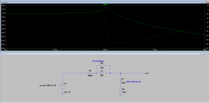
My simulation looks as follows:

It gives a Q of almost 30! I used a series resistance for the inductor of 500mOhm since the majority of beads on digikey was in the range of 300-600mOhm.
My suggestion would be to use a parallel RC snubber network between the decoupling cap and the ferrite bead, but I almost never see this done. Why is this the case? Is it just component cost?
Many thanks!
First of all happy new year!
For my current project I'm trying to learn how to layout and design with good EMC in mind. I think it's core of a good design in general.
The current project is a digital receiver, DSP, DAC and preamp on one PCB (I didn't really know what category this falls in, but my problem is analog so I figured this category would fit best). The board clearly has high frequency and sensitive analog signals. I want to decouple them as good as possible.
When I read about decoupling online there are many different things I read. The one that makes the most sense to me is the one by Guido Tent (which can be found here: http://members.chello.nl/~m.heijligers/DAChtml/Supply_decoupling.pdf).
One thing Guido and all the other papers have in common is to use decoupling capacitors to short the RF current to ground (and thus not throught our sensitive circuit).
The other thing is to do is to use ferrrite beads in series with the supply line to reduce the RF current in general. This reduces the loop current and therefore the emissions caused by it.
In my eyes this creates an LC resonant circuit that peaks! Why are we okay with this?
I understand that the ferrite bead has some dissipating abilities and capacitors have some ESR, but if I simulate it in LTspice I still get quite a high Q.
My simulation looks as follows:
It gives a Q of almost 30! I used a series resistance for the inductor of 500mOhm since the majority of beads on digikey was in the range of 300-600mOhm.
My suggestion would be to use a parallel RC snubber network between the decoupling cap and the ferrite bead, but I almost never see this done. Why is this the case? Is it just component cost?
Many thanks!
EMI ferrite beads are usually very lossy as frequency increases, so at higher RF freqs they look mainly resistive (100 ohms or so is typical), and the LC circuit Q is thus very low if the would-be resonant frequency is high enough. Typical uses for ferrite beads is to stop VHF oscillations (100's of MHz).
On cables ferrite cores are specifically used to reduce the common-mode RF current travelling along/over the cable which would radiate EMI.
On cables ferrite cores are specifically used to reduce the common-mode RF current travelling along/over the cable which would radiate EMI.
EMI ferrite beads are usually very lossy as frequency increases, so at higher RF freqs they look mainly resistive (100 ohms or so is typical), and the LC circuit Q is thus very low if the would-be resonant frequency is high enough. Typical uses for ferrite beads is to stop VHF oscillations (100's of MHz).
On cables ferrite cores are specifically used to reduce the common-mode RF current travelling along/over the cable which would radiate EMI.
Where is my model flawed then? How should I model a ferrite bead? Because if the series resistance changes the LF also changes which is not the case (as far as I understand).The parallel resistance seems to have little effect up until much higher frequency.
Thanks for the answer though!
EDIT:
Added image of my simulation in case the link dies for future reference.
Attachments
Last edited:
Depending on the type of ferrite bead and type and value of capacitor, you can indeed get fairly high-Q resonances. Usually there is some frequency in the megahertz range above which resistance dominates. See for example the impedance graphs in https://www.farnell.com/datasheets/1914683.pdf ; when R > X, you have something that's closer to a resistor than to an inductor.
By the way, cheap aluminium electrolytic capacitors (preferably with low working voltages) are quite useful as dampers, although an RC network is indeed more predictable.
By the way, cheap aluminium electrolytic capacitors (preferably with low working voltages) are quite useful as dampers, although an RC network is indeed more predictable.
Ferrites are not linear, frequency-dependent and some are not even explainable without quantum effects, such as the sorts used in circulators and isolators which violate the principle of reciprocity, so I suspect existing LTspice models are not very good.
In practice for VHF and UHF work ferrite beads are added if oscillations are discovered or suspected, because its easy - trial and error basically. DC offset affects the ac behaviour markedly with some ferrites (some change properties permanently if exposed to strong magnets too).
For high-speed decoupling in logic circuits everything that matters is up in the 100MHz+ range BTW.
Last edited:
Depending on the type of ferrite bead and type and value of capacitor, you can indeed get fairly high-Q resonances. Usually there is some frequency in the megahertz range above which resistance dominates. See for example the impedance graphs in https://www.farnell.com/datasheets/1914683.pdf ; when R > X, you have something that's closer to a resistor than to an inductor.
By the way, cheap aluminium electrolytic capacitors (preferably with low working voltages) are quite useful as dampers, although an RC network is indeed more predictable.
Well said, chip ferrites especially can't be trusted blindly. I prefer to use the RC network or a tantalum cap instead of a crappy electrolytic.
The article referenced isn't wrong but it's a bit old and I am not sure I agree with every little detail.
Use a scope.
This blah blah is useless.
Better be very careful that you're using the scope correctly - the probe and probe mounting is critical.
Use a scope.
This blah blah is useless.
I will use a scope, but I want to aim for a board that works in one go (I know this probably won't happen, but if you don't try you will never get it).
I figured that since these things are so often used, there might be some great theory behind it that I am lacking.
Also, like Chris mentioned, a scope is only helpful if you measure correctly!
Usually there is some frequency in the megahertz range above which resistance dominates. See for example the impedance graphs in https://www.farnell.com/datasheets/1914683.pdf ; when R > X, you have something that's closer to a resistor than to an inductor.
Do you mean those graphs on i.e. page 17? Cause it's about the only graph that has a comparison with a resistive element.
How would you read the resistance from an Impedance graph? I understand that if the curve rises it's inductive and if it drops it's capacitive, but I do not see how you can read resistive values from there (besides a very rough indication based on Q).
I am considering just placing a footprint of an RC network (as solution C suggest in this paper suggests: https://www.analog.com/media/en/technical-documentation/application-notes/AN-1368.pdf). If I feel like I need it, I can easily add the parts and If I don't need it, I can always remove them.
For example, on page 66 (according to the pdf viewer) or 64 (according to the page numbering) you find this graph with the resistance, reactance and magnitude of the impedance for a BLM18RK102SN1. Above 18 MHz, R exceeds X, but the magnitude of the impedance keeps rising up to about 120 MHz.
Attachments

No.Are you aware that LTSpice has a ferrite bead component in it's library?
Yes, there is, in Component: FerriteBead.Are you aware that LTSpice has a ferrite bead component in it's library?
Then you can select among a bunch of Wurtz Electronik parts going from 0.016 μH to 14 μH.
Ah!For example, on page 66 (according to the pdf viewer) or 64 (according to the page numbering) you find this graph with the resistance, reactance and magnitude of the impedance for a BLM18RK102SN1. Above 18 MHz, R exceeds X, but the magnitude of the impedance keeps rising up to about 120 MHz.
This explains a lot! The values are dynamic and this gives a great indication of how I should threat the ferrite bead.
I knew they were non-linear, but I thought it was just due to saturation (and therefore just current flowing through).
Are you aware that LTSpice has a ferrite bead component in it's library?
I was aware of that, but I wanted a generic ferrite bead and there was no model with the value I needed. That's why I looked into how those models look, but they are very dynamic and it makes my simulation model incorrect.
I think I understand how to go on with my project. Thanks everyone!
- Home
- Source & Line
- Analog Line Level
- Resonance in Decoupling Circuits