I'm conflicted over whether or not to include resistors in the output stage of my amp. The reason I want to is because it would make it very easy to bias. The reasons I don't want to is because I think I may reduce output impedence. Also, the output devices (TIP35/TIP36) have their collectors tied together because they're mounted on the same heatsink with no insulation and adding resistors would force me to change this. I'm not sure if it would really change impedence though. An amp with no resistors would act similarly to an amp with resistors and slightly higher rail voltage, right? Do resistors make a difference in an amp with very high feedback?
Push-pull emitter-follower outputs stages should have low value resistors in the series with the emitters. Without them bias current will be very sensitive to temperature changes and thermal runaway will be almost guaranteed.
The resistors won't affect output impedance if they are within the NFB loop.
The resistors won't affect output impedance if they are within the NFB loop.
My final output stage is common emitter, the PNP emitter is on the + rail, the NPN emitter is on the - rail and the collectors are the speaker output.
So if I add resistors, it would look something like this from the top down:
+ Rail / PNP Emitter
Resistor #1 / PNP Collector
Resistor #1 / Speaker Output / Resistor #2
Resistor #2 / NPN Collector
- Rail / NPN Emitter
For each side, I would take feedback from the point where the collector and the resistor meet, right? If I took it from the speaker output, it would defeat the purpose of having them there to begin with.
No, feedback is taken from the speaker output. You're on the safe side if you do it like everybody else.
Otherwise you would end up with two feedback signals anyway 😉
If the resistors are within the feedback loop, the output impedance won't change much. If they are outside (as you suggested), the amp's output impedance will be about the same as the value of the output resistors. How many output devices are parallel on each rail in your design? If it's more than one, you will definitely need those resistors as they reduce the effect of mismatched paralleled devices.
A common emitter output as you describe still need emitter resistors for the output transistors, so between emitter and supply rail, unless it is a compound stage (NPN driver with PNP output for the push, the opposite for the pull) with emitter resistors on the drivers and the collectors of the ouput transistors connected to the emitters of the drivers. Anyway you will need some emitter resistor somewhere for local feedback to stabilize the bias current.
Resistors in series with collectors of the output stage have no effect on output impedance. These resistors generally have the disadvantage of reduced headroom and increased dissipation.
I don't see how it would ease your biasing. Collector resistors have no influence on the idle current of your output; it will only change the collector voltage not the current. Or you have something completely different in mind than I have from your description.
Steven
AMT-freak said:... How many output devices are parallel on each rail in your design? If it's more than one, you will definitely need those resistors as they reduce the effect of mismatched paralleled devices.
Current sharing will not improve by collector resistors, since they will give no feedback. For sharing you need emitter resistors.
Steven
Right, just read the first post with the classical topology in mind and didn't see the contradiction 😉
I am only using one set of output devices. I'm looking for global feedback here. An emitter resistor will do nothing for a complementary pair. The reason a collector resistor will help is because if I tie the output stage's collector to the previous stage emitter, that will effectively increase the operating point of the first transistor stabilizing the bias. I am biasing one transistor through another and because gain is so high, I need a way to control the bias.
Solid Snake, I think that you are crazy. ;-) This is the situation: YOU MUST USE A SMALL VALUE EMITTER RESISTOR IN EACH OUTPUT EMITTER. Yes, if you are an expert, perhaps you can design advanced thermal/ DC output current sensing and avoid the emitter resistors, BUT you better know what you are doing. What happens is that the Vbe junction heats up in operation and draws more average current, then this extra current heats up the Vbe junction even more, and even more current flows. Sooner or later, flash/bam almost all circuits blow up. Please keep this in mind. There is no point in using a collector resistor, except a high value one (or 2) to provide feedback to the input, and it won't have any significant current flowing through it.
OK, this is a common emitter circuit. It is biased from ground. This means that there are about 16v across the biasing resistor. If the output transistor gets hot and it the vbe voltage goes down, the base current will increase by so little it's not even worth mentioning.
Solid Snake,
A common emitter output stage has the principal output device collector to output, and the emitter of the driver also to output.
Consequently the bias voltage is determined by the voltage between the driver bases, which then gives you two Vbes of bias voltage. It is NOT determined by the output devices, and thus the advantage is that even if the outputs get very hot, the bias current won't much increase because the drivers likely will remain fairly constant in the Vbe at idle.
However, the problem is this; the drivers are smallish transistors. Their Vbe is not varying by a great deal over the range of operation of the amplifier, perhaps from 600mV to 630mV at full output. This has repercussions for bias stability.
It means that unless the Vbe multiplier, the bias generator, very closely tracks the heat on the DRIVERS (NOT the outputs) you could have a very tetchy adjustment on your hands.
My own experiences suggest that bias voltage is critically sensitive on CFP output stages. Very slight deviations and the output goes thermonuclear. While there are means of adjusting the tempco of the Vbe multiplier to match the drivers, it's very difficult to precisely match over the entire thermal operating range of the drivers, even though this range is rather less than the outputs.
Don't do it. Use resistors on the collectors of the outputs, and link the emitters of the drivers directly to the collectors of those outputs. These resistors are inside the global feedback loop, and therefore their series resistance is greatly ameliorated by the feedback factor, normally a factor around 40dB and higher. I agree emphatically with John.
I would also add that emitter followers, particularly Self's Type II, sound a lot better.
Cheers,
Hugh
I agree 3 with john and AKSA. Designing a CFP is the most difficult job of all. Bias voltage is very sensitive to thermal coupling. I've never tried it without the output resitor and I will never do so.
Common emitter stages are much better to handle. And - last but not least - CFP has a very strange input behavior of the input resistance wich causes a lot amout of crossover distortion.
Common emitter stages are much better to handle. And - last but not least - CFP has a very strange input behavior of the input resistance wich causes a lot amout of crossover distortion.
Solid snake, I suggest that you verify this by practical tests.Solid Snake said:If the output transistor gets hot and it the vbe voltage goes down, the base current will increase by so little it's not even worth mentioning.
"Increase by so little",

If you can prove this true you can apply for the Nobel Prize.
peranders said:"Increase by so little",
If you can prove this true you can apply for the Nobel Prize.
solid snake is correct in his statement for that particular set-up where the collector resistor essentially acts as a local feedback for pre-driver bias current.
emitter resistors for such a set-up will help but not as much.
I think for a CFP, a collector resistor is a must for any stability, not just Iq stability. Plus, it also works as a sampling resistor for a v-i limiter.
You have to see where the bias comes from to know what it will increase by. Take this simple circuit with an NPN transistor with a grounded emitter and load on the collector. Now say the bias comes from +20v through a 4.7K resistor. When the resistor is nice and cool and conducts at 0.7v, the base current is: 4.10mA ((20-0.7)/4700). Now when the junction heats up enough so that the transistor conducts at 0.6v the base current is now 4.12mA ((20-0.6)/4700). Hardly enough to cause any thermal runaway.
Solid Snake said:Hardly enough to cause any thermal runaway.
that calculation is a little missleading as you are calculating the Iq for the pre-driver, not the Iq for the output device.
the Iq on the output device will be determined by the Ic of the pre-driver and the resistor on the collector of the pre-driver (which in turn determines the Vbe of the output device).
I will try to see if I can simulate that.
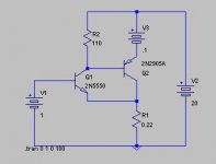
here is the circuitry I had used for simulation purposes. V1 is used to simulate Vbe declines as temperature goes up.
1) with V1=0.1v (cold output devices), current going through R2 is about 9.95ma, and current through R1 is 1.08a;
2) with V1=0.1v (hot output devices), current going through R2 is 9.0ma, and current through R1 is 1.09a.
so the use of a collector resistor (R2) is quite effective in regulating Iq through the output device (Q2).
in my view, CFP is superior in thermal protection but worse in stability (at least for mosfets. It is hard to get a mosfet cfp to work using irf devices).
Attachments
I got it wrong. It should have read like this:
I also tried V1=0.2v, Ir2=10.8a, Ir1=1.07a.
so as far as Iq is considered, CFP is very stable.
millwood said:1) with V1=0.1v (cold output devices), current going through R2 is about 9.95ma, and current through R1 is 1.08a;
2) with V1=0.0v (hot output devices), current going through R2 is 9.0ma, and current through R1 is 1.09a.
I also tried V1=0.2v, Ir2=10.8a, Ir1=1.07a.
so as far as Iq is considered, CFP is very stable.
Hi, been lurking a while but decided to join as I'm missing out on too much good stuff 🙂
I have been having thoughts about using multiple output devices in CFP configuration (1 driver and 'a few' mains).
I can see that an 'output' resistor (0.22 ohms in millwood's schematic above) is useful for bias stability and, how it acts as the emitter resistor in 'whole device' terms, but if you are paralleling main devices, would you need individual device emitter resistors as well? Rod Elliott uses this method for his P27 amp, but Doug Self just parallels without resistors in his load-invariant amp. Surely, if you look in macro terms / at individual device level, an emitter resistor will promote current sharing?
Also, I'm a bit dubious about all the current of lots of main devices going through one single (0.22 ohm) resistor, so I have devised the scheme below. Grateful for any comments.
An externally hosted image should be here but it was not working when we last tested it.
- Status
- Not open for further replies.
- Home
- Amplifiers
- Solid State
- Resistors in the output stage