Hello all. I am trying to put together a BOM for a 12AX7 Baxandall tone control board that I bought quite some time ago. I can figure out most of the components by reading the rather good information in the silk screening on the board, but I am not experienced enough to determine resistor wattage by "eye".
Here is a pic I found of a finished board. If anyone could help me determine wattage values of the resistors it would be a huge help to me.

What I see are "small, medium and large" - I could assume 1w, 3w and 5w respectively, but I don't want to assume.
Here is a pic I found of a finished board. If anyone could help me determine wattage values of the resistors it would be a huge help to me.
What I see are "small, medium and large" - I could assume 1w, 3w and 5w respectively, but I don't want to assume.
I would connect it to a power supply and measure the voltage drop across the plate resistors
(and cathode follower resistors if any), and calculate the power dissipated in the resistors.
Then use a derating factor of two to four to find the ones to buy. With 12AX7 tubes, the plate
resistor dissipation is unlikely to be more than 0.5W, so 1W to 2W parts for those should be fine.
Other resistors can be the usual 0.25W types, although 0.5W are also fine.
Sorry, I wasn't clear. My board has no components at all right now, so connecting it to a power supply wouldn't be very helpful. 🙂
The pic is a sample I found of a populated board and I am trying to figure out what wattage of resistor to purchase for each. I have no idea how to identify resistors by name (plate resistors, cathode follower resistors).
I see 3 sizes of blue resistors, and then the pink ones and the green ones. I don't want to just "guess" the wattage values of them.
I just dug some 5w parts out of my parts bin and they do look to be a bit too large for the green or pink positions.
So 2w parts for green, pink and large blue positions. 1w parts for medium blue, and 1/2 watt parts for small blue.
Sound reasonable?
So 2w parts for green, pink and large blue positions. 1w parts for medium blue, and 1/2 watt parts for small blue.
Sound reasonable?
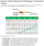
With the chart below and a ruler (and if your eyes are like mine, a magnifying glass), you should be able to figure their ratings.What I see are "small, medium and large" - I could assume 1w, 3w and 5w respectively, but I don't want to assume.
Just measured 12AX7 outer pin socket diameter at around 13mm for comparison, so if the chart below is correct, the row of resistors next to the octal sockets would all be 2 watt.
Attachments
Last edited:
I have some 1/4 watt parts here that are obviously too small, so based on the chart I was able to determine with reasonable certainty that the smallest resistors should be 1/2w, the mediums will be 1w and the largest will be 2w. This coincides with Rayma's initial response, so I am pretty confident that this is sorted.
Thanks again, everyone.
Thanks again, everyone.
As the 12AX7 outer pin socket diameter is around 13mm, so if the chart posted is correct, the row of resistors next to the octal sockets appear to be 15mm long, 2 watt.
The 11mm resistors above the right socket would be 1 watt, and the smallest resistors appear to be 8mm, 1/2 watt.
Unless they are those newer high power resistors ;^).
The 11mm resistors above the right socket would be 1 watt, and the smallest resistors appear to be 8mm, 1/2 watt.
Unless they are those newer high power resistors ;^).
Thanks again!
While I have you all here, can anyone offer any insight into the odd little capacitors in the bottom left quadrant of the board (in the previous pic, little brass coloured ones)?
On the board, these positions are marked with SANGAMO 100p / 400v
The value is obvious, but Mouser does not carry that brand and I am trying to choose a suitable replacement. Just go with a WIMA film cap, or do I need something specific here?
For L = body length in mm:
L^2, divided by 120 is a safe power rating
You will find parts rated for much higher power in the same size. Obviously they must run HOT. On this too-crowded board you do not want to run that way. i.e. if you have an 11mm part which claims 3W, settle for 1W.
It really helps to have a schematic(??) and to obey Ohm's Law.
Plate resistors are many-K. Cathode resistors are few-K. Grid resistors 1Meg.
If the power supply is 250V, and the tube were dead short, 250V across a 100k plate resistor is 0.625W. In guitar amps we use 1W just-in-case a tube shorts-out and it is not noticed for weeks. Or 2W because g-amps tend to run over 250V. In normal operation the 100k and the tube "split the voltage", and we normally find 100V-140V on 100k, less than 0.2W.
There are reasons to over-size beyond functionality, robustness, and long life. Physically very small resistors hiss more. But next to a 12AX7, none of the leaded types should be hissy. (Except carbon-comp.)
SANGAMO made power meters. I am aware they had a cap factory but nothing magic. A 100pFd is almost certainly a ceramic. Below 1,000pFd ceramic is as nearly perfect as any cap. Much over 1,000pFd you have to check if they use a "hot" insulation which may distort or drift (and then film makes sense).
Last edited:
You would have made our life much easier and answers more accurate by posting the actual schematic.Hello all. I am trying to put together a BOM for a 12AX7 Baxandall tone control board that I bought quite some time ago. I can figure out most of the components by reading the rather good information in the silk screening on the board, but I am not experienced enough to determine resistor wattage by "eye".
Just sayin´ 😛
Ouch!
Just wondering how will you build that project or even order parts . 😕
Meaning: why worry about wattage rating if you don´t even know resistor **value**?????? 😱
Just wondering how will you build that project or even order parts . 😕
Meaning: why worry about wattage rating if you don´t even know resistor **value**?????? 😱
As I already explained, the resistor (and all other components) values are clearly marked on the board.
Here is a pic of my actual PCB. 90% of it is obvious. I only had a few questions that needed figuring out.
Sorry if this is too low brow for you. I aim to make it work, regardless of how stupid I am.
I already have a complete BOM saved on Mouser, based on the help I have received from the others earlier in this thread and my own "Forrest Gump ingenuity".
Attachments

Last edited:
- Home
- Design & Build
- Parts
- Resistor Wattage