Burmester 785 preamp
Something starting with a 6, the temperature coefficient is between -50 and +50 ppm/K.

It would be interesting if you can draw at hand a schematic of the components involved. It can give us an idea of its value.
In any case, consider that highly probably, those resistors are victims of any other part in the circuit became shortcircuited, semiconductors or the blue tantalum near them. So I suggest to search for components damaged in other part of the PCB.
In any case, consider that highly probably, those resistors are victims of any other part in the circuit became shortcircuited, semiconductors or the blue tantalum near them. So I suggest to search for components damaged in other part of the PCB.
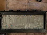
Here's another photo, maybe someone with a large monitor can make it out.
https://hifi-inside.com/hifi-ht/burmester/preamplifier-11
https://hifi-inside.com/hifi-ht/burmester/preamplifier-11
Good point Osvaldo , thanksIt would be interesting if you can draw at hand a schematic of the components involved. It can give us an idea of its value.
In any case, consider that highly probably, those resistors are victims of any other part in the circuit became shortcircuited, semiconductors or the blue tantalum near them.
Thanks Rayma , I did try the photo search but there aren’t any that are clear enough to see , plus most others only have 2 resistors in the same area whereas this 785 has 3 for some reason.
My suspicion is that those R's are between 10 and 100R to decouple the Vcc and Vee pins of the opamp we can see close to them. If the chip became damaged by severe overload of their inputs, those resistors became smoke.
Well I guess I could start with 100’s and work back ( after replacing those tantalum caps )
My suspicion is that those R's are between 10 and 100R to decouple the Vcc and Vee pins of the opamp we can see close to them. If the chip became damaged by severe overload of their inputs, those resistors became smoke.
It would have to be sixty-something ohm then. As they look like ordinary 0.6 W, 1 %, 50 ppm/K metal film resistors, they probably had E96 values. That narrows it down to:
60.4 ohm
61.9 ohm
63.4 ohm
64.9 ohm
66.5 ohm
68.1 ohm
69.8 ohm
Chances are that all these values would work fine, once whatever made the resistors burn has been solved.
Thanks Marcel .
I can say that currently the volume pot does nothing.
I’m no expert by the way!
Should I replace the tantalum caps and those 1000uf electrolytics ?
There is also the possibility that the volume pot is faulty as it appears to be a common fault, it was seized until I used some contact cleaner on it .
I can say that currently the volume pot does nothing.
I’m no expert by the way!
Should I replace the tantalum caps and those 1000uf electrolytics ?
There is also the possibility that the volume pot is faulty as it appears to be a common fault, it was seized until I used some contact cleaner on it .
Discard volume pot.
I insisto on that with a schematic or a pic of the downside may help much.
I insisto on that with a schematic or a pic of the downside may help much.
Yeah, it seems to me that l was right. Looks to be in the power lines of the IC below them. Replace the IC and or tantalum units and the resistors for new 68 ohms 0.5W. Standard 5% are values OK, no need for precision units.
Looking at the photo's, I would say the resistors are part of the psu and the chip in the metal can with heatsink is more than likely a dual voltage regulator - all located close to the transformer, caps and mini diode bridges.
Looks like the 2 burnt resistors are fed from the +/- voltage rail on the psu caps feeding the IC input. So maybe a dead IC regulator chip - if you take the heatsink off Andy, you should be able to read the chip type on the side of the metal can.
Yes, get rid of the tantalums.
Looks like the 2 burnt resistors are fed from the +/- voltage rail on the psu caps feeding the IC input. So maybe a dead IC regulator chip - if you take the heatsink off Andy, you should be able to read the chip type on the side of the metal can.
Yes, get rid of the tantalums.
Last edited:
Something shorted for sure.
A tantalum cap or a regulator or a bridge rectifier. My guess is 6.8 ohms
A tantalum cap or a regulator or a bridge rectifier. My guess is 6.8 ohms
If those are series resistors in the supply lines, odds are they are under 10R.
Quite easy to follow the tracks on the back of the board. You can see 2 secondary windings , each feeding a small round diode bridge, plus and minus on each are filtered by 1000uF caps and those 2 points feed the 2 burnt resistors which then feed the IC +/- input with each point having a tantalum to gnd. Then there are 2 more tantalum's probably on the IC regulated voltage output.
So, either the tantalum's are down to gnd, or the IC is cooked - or both maybe. I agree, these burnt resistors are likely 6R8 in value.
I would replace all tantalum's with electro's and also replace the 4 off 1000uF/40V axial electro caps, given the age of the preamp.
I suspect the diode bridges might be OK, but can be checked with a meter, these could also be replaced - they are still available in that style.
It will be interesting to see what type the IC is, there were not too many dual voltage regulator chips around in those days - 45+ years ago now.
I think this can be helpful:

My bet:
Blue, Grey, Brown or Black, Gold, Brown
Which is: 68 Ohm +-1% or 68,1 Ohm +-1%
My bet:
Blue, Grey, Brown or Black, Gold, Brown
Which is: 68 Ohm +-1% or 68,1 Ohm +-1%
Last edited:
- Home
- Source & Line
- Analog Line Level
- Resistor values (no schematic available)