> no idea how to produce a nicely formatted table.
Cheap trick: use underline "_" instead of spaces " ". In most fonts, " " is very narrow, "_" is more-like the average character width. Some adjustment may still be wanted when you have "0" and " 74,881.00" in the same table.
dB____RATIO______R1_____________R2
__0____0.00%_____-______________100,000.00
_-3___29.21%_____29,205.00______70,795.00
_-6___49.88%_____49,881.00______50,119.00
...
-63___99.93%_____99,929.00______71.00
-66___99.95%_____99,950.00______50.00
-69___99.96%_____99,965.00______35.00
There is a table-tool in forum code but row/cell tags are not explained and you probably drown in tags.
Last edited:
I do not know what a "linear LADDER tone control might be.
You can NOT arbitrarily replace simple pots with ladders. Even for flat loss there are consequences (typically low input impedance). Simple tone controls are ALL about impedance relations between resistors and capacitors (maybe inductors). If you change the resistors to ladders, you have a new analysis to do just to get the tone-shapes you want.
> Maybe because he wants to build an active Baxandall type tone control?
That is the only thing which makes sense to me. (I have NOT studied all possible tone controls.) (Designs based on bandpass filters can use ladders for gain control, but the buffering and mixing and boost/cut bits make it a mess.)
In the Bax, you open the pot, chop it into how-many pieces, nail those bits to your switch contacts. Bingo, instant linear step pot.
An obvious objection is that the Bax (or any) with 1 Meg pots has high hiss voltage. Maybe over 6uV in the audio band. It needs to be after some gain. Much lower value resistors are not much lower hiss voltage, and the Bax is already impedance-challenged at its input. For 1Meg pots, Zin is 100K mid-band and lower in treble. It needs a very low-Z drive. (Even experienced designers have overlooked this, commercial designers have looked the other way.)
_I_ thought I would come back to more interesting questions. A Bax in a hifi gets used two ways. Little part-dB trims for sonic balance, or big 12dB boost for Party Music (or heavy cut for 78s or LP grooves full of weed dust). So "linear" may not be best. 20dB boost with 11 steps is 1.8dB per step. But we may want <1dB precision for fine trim, and >3dB unprecision for big boosts (cuts). But I guess we aint there yet.
The functional difference is the source sees a constant load where as a series attenuation does not.
About 40 years ago I wrote some notes on ladder attenuators. I liked to start with the series resistor Rs and the attenuation per step A. Choosing a Rs =10K and 2dB A~=0.8 (=1.94dB) you get Rend= Rs*A/(1-A), 10K*0.8/0.2=40K and Rp=Re/(1-A), 40K/0.2=200K. A 10dB ladder can be Rs=10K,Rp=6.8K and Re=4.7K, but 10dB/step is not useful without an additional "Vernier" adjustment, say 1dB/step (A=0.89).
But it is easy to outperform such ladders with a few binary steps, although care must be taken to avoid glitches between "codes". Momentary mute or Off before On timing should cover that problem. For audiophile use, that would probably have to be ~6 relays for 64 positions/codes, but I once professionally used a 8 bit multiplying DAC for a telephony gadget that had no noticeable distortion issues in that application. I spent some time considering a log device but found that a more common linear DAC provided all the resolution I needed, ie using selected codes for +/-15dB in 1dB steps.
Today, we do most "pre-amp" functions in software. 16 bit resolution is about 96 1dB steps.
Last edited:
Nikolas, …
You (like many, so don't feel bad) are making the fundamental mistake of calculating the absolute precision of the resistors in the chain, without acknowledging 2 other facts. First, that the human ear simply can not detect the difference of 0.2 dB (most ears have a hard time with even 0.5 dB), and second, the ACTUAL dB value per step is of no particular importance (to attain 0.01 dB resolution), in light of there being completely arbitrary 'steps' in the ΔdB-per-step values you set out to achieve to begin with.
Better is just to build a pair (or more) of volume-control stepping switches, with nicely matched resistors at every position. People (including you) using the things won't be particularly cued into whether step 13 is (–23 dB) or (–24 dB) or (–22 dB). But they will be, should there be an inaccuracy in the difference in dB between channels!
So, my advice after all that is: lose the 'b' resistors entirely. Just buy the E96 resistors that most closely match those needed (say 10 each), then one evening with a 4½ digit DVM, while watching 'the game' or your favorite show, test them all … and 'bin' them into close matches. It is relaxing and fun. When it comes time to use them, you'll have a bunch of well matched pairs.
Lastly, attempting to keep exactly-and-precisely 100 kΩ of total ladder load is also a non-starter! The source hardly cares one twiddle. The destination though, depending on the nature of its input stage, may well care quite a bit between a 100-to–50 kΩ effective source impedance (when the attenuators aren't attenuating much), and the much much lower effective source impedance when they are heavily attenuating.
Sorry to be a party-pooper.
Its just that many decades back, I had another fine (RIP) fellow here set me straight.
And after weeks of esquisitely careful testing … it turned out he was exactly right.
Yours,
⋅-=≡ GoatGuy ✓ ≡=-⋅
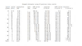
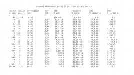
The reality of the calculations
The attenuation numbers on the third and fourth column are based on Rgnd values and the assumption that the combined resistance Rgnd + Rserial stays at 100 kΩ. Calculators give more decimals, but I rounded to two decimal numbers, which is enough to show the small differences in the steps. That is all about those attenuation numbers.
The Rgnd resistors that were picked from E48 series are shown on the fifth column. This is a convenient way to design a stepped attenuator and the third and fourth columns show where that leads.
The later columns on the right describe how much resistance is left to the Rserial and how it is possible to achieve some precision if that is desired. So, if one wants to make the circuits with less components, just look at Rserial given on column six and see what is the closest value resistor available in the shop.
But there is more. If one wants more precision, the columns seven and eight show one possible way how to achieve that.
- Home
- Design & Build
- Parts
- Resistor Values for LINEAR Ladder Attenuator (not series Attenuator)