@ gilwe
The easiest option may in fact be to add at least one set of RCAs on the back panel, so that loading plugs can be made up. Just a suggestion. If possible take a few close-up photos of the RIAA area on the board and post them here.
I dropped an e-mail to YBA yesterday, asking them if there is a user manual available. Maybe they'll answer.
Kevin
There appear to be four sets of phono sockets there already ( the output sockets are at the other end) so maybe one pair can be allocated to loading?
A shot of the rear of phono stage might be handy.
With this single sided PCB it will be very simple to extract the circuit diagram.The ports on the rear panel are:
Tuner In
Aux In
Tape In
Tape Out
Phono In
Amplifier Out
I wonder if the internal MC/MM switch doesn't switch capacitance then?
(based on that only the resistor is exchangeable)... How can this be tested?
That takes away all the guesswork.
Does probably take less than 15 minutes to unravel the part around the phono input.
Hans
Do you mean that the switch changes resistance? This would make sense as capacitance is normally more effective for MM/MI carts.
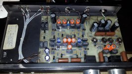
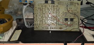
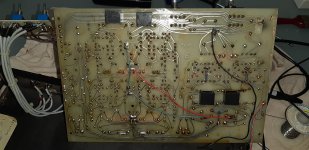
gilwe, is there any chance of unbolting the PCB and taking a closeup picture of the bottom, and of the top. It will of course mean desoldering the cables for the Tape Out, RIAA input, Pre Out and power so that the board can be flipped up. Of course the volume and balance knobs and pots will also have to be loosened so that the board can move backwards into the box for the flip-up.
Kevin
Kevin
Last edited:
absolutely no need to do all that.gilwe, is there any chance of unbolting the PCB and taking a closeup picture of the bottom, and of the top. It will of course mean desoldering the cables for the Tape Out, RIAA input, Pre Out and power so that the board can be flipped up. Of course the volume and balance knobs and pots will also have to be loosened so that the board can move backwards into the box for the flip-up.
Kevin
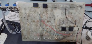
One can see the traces from above and with the help of a multimeter all traces can be reconstructed.
Hans
So where’s the circuit diagram.
Give me a real good picture of the PCB’s phono part and I’ll do it.
Hans
Give me a real good picture of the PCB’s phono part and I’ll do it.
Hans
Guys, thanks so much. I can surely do that, but before, here's a short update:
I just replaced the MC cartridge (AT30E) to an MM (Shure M44E), opened up the unit and turned the MC/MM switch to MM. It sounded dull with no hi-end. Then I simply took these two 1k resistors out of their sockets, and viola, the highs are back and it sounds "correct".
I think the sound is even a little too "hot", with it clipping very slightly with some recordings, but I'm not entirely sure, as it might just be the alignment and/or cartridge. Both cartridge and needle are new though, and I set the weight to 3 grams as this is the max my Dual 505 allows, and the specs for the cartridge and N44C needles say 3-5 grams.
Placing 47K resistors in the sockets makes it dull again, and turning the switch to MC makes it highly distorted.
Do you still need the pictures of the board or does this solve the mystery?
I'm basically waiting for a delivery of caps to recap the board, then I can also take all closeups.
Last edited:
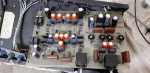
OK I found something. It this good?
I've been listening to a few records, and it sounds pretty correct. The high end may be a little too prominent though, I'm not sure if I was supposed to place any other resistors in place of the ones I took out, or leave them completely out...
I've been listening to a few records, and it sounds pretty correct. The high end may be a little too prominent though, I'm not sure if I was supposed to place any other resistors in place of the ones I took out, or leave them completely out...
Attachments
Last edited:
And the input impedance is now ?
For a MM it should be around 47K ohms which is recommended for that cartridge ,if it is 100K ohms that might account for the "prominent high " but what is the input capacitor ?
Capacitance =150pf-300pf (depending on your taste of balance).
For a MM it should be around 47K ohms which is recommended for that cartridge ,if it is 100K ohms that might account for the "prominent high " but what is the input capacitor ?
Capacitance =150pf-300pf (depending on your taste of balance).
MM input impedance with no resistors in sockets, is 100Kohm.
Should I also check for the capacitance value across the inputs?
Should I also check for the capacitance value across the inputs?
Last edited:
Keeping in mind post #14, all you know is that it is smaller than or equal to 100 kohm without resistor.
Its what the cartridge first sees as a load impedance and parallel capacitance any other variation after that relates directly to the amplifier design.
Measure the capacitance of the input ---for that cartridge it should be in the range I posted .
Measure the capacitance of the input ---for that cartridge it should be in the range I posted .
The 47 kohm resistance is meant to damp a resonance in the 10 kHz...20 kHz range to some optimal quality factor. When there is an AC coupling cap in series with the resistor that has a negligible reactance at 10 kHz and above, the resistor will damp just as much as without AC coupling, you just can't measure it anymore with a DC ohmmeter.
I wouldn't be surprised if there were an 88.7 kohm bias resistor after an AC coupling cap, resulting in 47 kohm together with the 100 kohm before the AC coupling cap. In any case, it's all guesswork until the circuit is reverse engineered.
I wouldn't be surprised if there were an 88.7 kohm bias resistor after an AC coupling cap, resulting in 47 kohm together with the 100 kohm before the AC coupling cap. In any case, it's all guesswork until the circuit is reverse engineered.
Have a look at designs by D.Self/JLH etc all have similar values relating to the type of cartridge used of a standard value which is exactly the resistance value I posted ( or near it ) for a normal MM.
After any DC blocking capacitor at the input the values I gave are the same as many designs in articles in EW by both audio engineers.
I get what you are saying --is there a blocking capacitor in series first at the input ?
After any DC blocking capacitor at the input the values I gave are the same as many designs in articles in EW by both audio engineers.
I get what you are saying --is there a blocking capacitor in series first at the input ?
- Home
- Source & Line
- Analogue Source
- Resistor value to swith Phono stage from MC to MM?