1 ohm seems OK, your meter reading would have included the resistance of the leads.
Now measure the resistance of the tweeter, and use this calculator to work out your new resistor:
L pad calculator - attenuation dB damping impedance decibel loudspeaker speaker voltage divider - sengpielaudio Sengpiel Berlin
(Might be simpler to buy a few preferred value resistors & swap them until you find the one you like, say 1.5, 1.8, 2.2)
Last edited:
I would go Pete's simple way, macson66 - replace the 1 ohm resistor with a 2.2 ohm one.
If the attenuation is still not high enough, wire your current 1.0 ohm resistor in series with the 2.2 ohm resistor to give a total of 3.2 ohm. That should be enough to do the job.
If the attenuation is still not high enough, wire your current 1.0 ohm resistor in series with the 2.2 ohm resistor to give a total of 3.2 ohm. That should be enough to do the job.
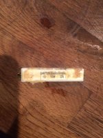
The resistor is a large physical size because it has to convert the unwanted audio signal to heat.as it states 1ohm I'm a little confused - for the size of it is that what it means?
It has a resistance of 1.0 ohm and can dissipate up to 10 watts of heat.
All the ceramic resistors of the 10watt verity are that size, whether it's 1 ohm or 100. Definitely just grab a bunch of values and swap them in till your happy. They're not very expensive for what you'll gain in happiness with your speakers.
You both just answered my next question - I'll try several around the values you stated and see how I go. Thanks all for your help - will post just for the record as to what I ended up doing.
Sounds like 1.5 Ohms to me. Just be aware that errors do creep in when measuring very small resistances.
To be absolutely sure it would be better to put it in a test circuit in series with a small lamp and a battery and measure the current and voltage in the circuit.
To be absolutely sure it would be better to put it in a test circuit in series with a small lamp and a battery and measure the current and voltage in the circuit.
Last edited:
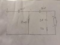
Not sure if anyone will see this as post somewhat finished but as a follow up I finally got round to trying different resistors which seemed to make no difference to the tweeter! On closer inspection I think my crossover is wrong. I've posted a pic where the dotted line is part of it and the 1 Ohm resistor is where it was put originally to help with the brightness. My query is the dotted line - should that be there and what is it achieving? If I remove it from the crossover the sound remains the same (to my ears) If I increase the 1 Ohm resistor to 4.6 Ohms (several resistors in series) the sound remains the same - Is this the correct point to put the resistors to lower brightness? Slowly getting my head around all of these things (at least a little bit) and as the dotted line is not on the original Schematic (I don't remember why it was put in) I think something is wrong with it. Does it look correct at a glance and should the resistor be at a different point to lower brightness? Thanks.
Attachments
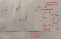
Unfortunately, that resistor is in a place that won't particularly affect the spl. I believe the previous responses here were based on the assumption that the 1 ohm resistor was in-line with the tweeter.
Typically, the 2 uF capacitor and 1 ohm resistor that are parallel to the tweeter provide some impedance compensation. Those small values will likely affect the rising impedance of a tweeter's voice coil only at higher frequencies.
The circuit is 3rd order, with what is often referred to as a Zobel (impedance compensation). However, the 50 uF and 25 mH values both seem a little large. It may be more likely that they are 5.0 uF and 0.25 mH.
Regardless of the actual values, the addition of a padding resistor, in-line with the tweeter will change the loudness of the tweeter. Attached is a sketch showing where to add a padding resistor to change the tweeter SPL. Start with a 1 or 1.5 ohm, and increase if/as desired.
Give that a try, and keep us posted. 🙂
Attachments
- Home
- Loudspeakers
- Multi-Way
- Resistor size unknown