I appreciate your analytical reply.The OP's question was a good one and deserves a serious, engineering based answer.
When I've needed a power resistor, I've always favored the type pictured because they are simply more believable than those that look like over grown non-power resistors. They are made to be screwed down to something as opposed to being suspended in free air for better air circulation and avoiding contact with a combustible base. They don't require a heat sink but can make use of one depending on actual power handling and anticipated ambient temperatures.
I promised an engineering based answer so I downloaded a data sheet of an example of that type of resistor and found the following at the bottom of it - derating curves based on ambient temperature and heatsink vs no heatsink. You can simply look at graphs, consider your ambient conditions, and make a judgment. It pays to overdesign with power resistors because if you don't they can get uncomfortably - even dangerously hot on a wood base in a hot climate without air conditioning. Home audio is obviously more forgiving than aerospace but it pays to be conservative.
The hardest thing to know is the actual power dissipation requirements. In general, a spice simulation is required. Its seldom worth the effort and even then that is a lot task of someone not trained in the art. For an L-pad, its easy as the amplifier's output is across the resistor pair and ohm's law suffices. I use Vituix and I see it recommends a power rating for Rs in a parallel RLC circuit where there will be significant dissipation but not for a series RLC where dissipation is significant only at or near resonance and then only at a low duty cycle for audio.
If you are concerned about the inductance, you can model it in the XO program and see if the L makes a difference in the response. Usually though, its easy enough to find a non-inductive resistor.
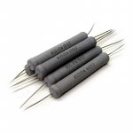
Many years ago, I stumbled into a cache of Dale 25W "NH" resistors (like the one pictured) at an electronics surplus store. They were dirt cheap, so I bought a bag full, and have utilized several in crossovers. I haven't done a scientifically controlled comparison, but it was hard not to notice that they sounded clearer than the cast resistors I'd
been using. It never occurred to me at the time that temperature would ever be a concern. That was 32 years ago.
I have no idea how they'd sound compared to some of the modern boutique types, but they've part of a set of speakers that has kept me intrigued for decades.

been using. It never occurred to me at the time that temperature would ever be a concern. That was 32 years ago.
I have no idea how they'd sound compared to some of the modern boutique types, but they've part of a set of speakers that has kept me intrigued for decades.
Thanks. I read that doc., about 10 years ago, when I decided to use them in my first outboard XO. I never found any info on the induction so that is why I measured them. You may have seen this but here are the measurements. Now this is an uneducated guess but it is low I doubt they have much of an effect on the sound.
RH-10 10W 1ohm 1% R=1.020 L= 5.3uH
RH-50 50W 1ohm 1% R=1.016 L= 5.34uH
RH-50 50W 2ohm 1% R=2.017 L= 0.3uH
RH-50 50W 2.2ohm 1% R=2.224 L= 0.4uH
RH-10 10W 1ohm 1% R=1.020 L= 5.3uH
RH-50 50W 1ohm 1% R=1.016 L= 5.34uH
RH-50 50W 2ohm 1% R=2.017 L= 0.3uH
RH-50 50W 2.2ohm 1% R=2.224 L= 0.4uH
I was using cheap power ceramic wire-wound resistors for all crossovers I'we build, as well as the type henrylrjr uses, until I tried these
non-inductive ones: Jantzen MOX RSS 5% 10W. I started to use them in a 2 way crossover - 15inch+1inch/Seos Horn, 12 db/oct + equalisation.
I have no measured proof if it 'sounds' better or not, but one strange thing happened: when I was replacing the bunch of wirewound resistors from the horn driver section (including the horn EQ resistor) with the non-inductive type (I added few in series to get a higher value), It was needed a bigger value to get the same perceived sound pressure level. Hope this helps. I have the resistors from a friend, but I discovered that Jantzen makes them. Real measured value under 5% precision in my case. The driver is Beyma CD10Nd and the horn is SEOS 15. Caps are Jantzen Superior + Intertechnnik Audyn Reference in eq part.
Attachments
Yeah, the data sheet says they're non-inductive so probably a non-issue for simple analogue audio circuits.Thanks. I read that doc., about 10 years ago, when I decided to use them in my first outboard XO. . . . . .
The standard square white cement style power resistors are capable of running hot enough to unsolder themselves when installed in PCBs with short leads. They also can discolor the PCB from the heat they release.
The result is that they are used in low cost crossovers. However some designers do design the crossovers to take advantage of the inherent inductance!
There are many lower inductance resistors such as Ayrton-Perry wound resistors. These use a winding technique to reduce the inductance.
https://en.m.wikipedia.org/wiki/Ayrton–Perry_winding
Another technique to reduce inductance is to use a higher resistance wire. However these types tend to have much worse temperature coefficients and can due to the thermal resistance changes increase distortion.
The other technique to reduce inductance is to use a “Shorted Turn”. Buy surrounding a coil with a conductive cover the magnetic coupling acts as a short circuit and results in lower inductance. There is some of this effect in the aluminum housed power resistors.
In addition such metal housed resistors may also use Ayrton-Perry winding techniques.
As to the importance of inductance even 2 microhenries would in theory affect changes in the highest frequencies of interest in the audio band of a passive loudspeaker crossover. In practice this low level of inductance will have virtually no effect as it is swamped by the inductance in most tweeters.
So folks who have the measurement gear find that different passive components do make a difference.
Last edited:
I missed that in the doc you provided. The doc states they meet military specs and the vishay model # will begin with ENH or ERH. The Vishay model # for mine are marked RH and the spec. sheet for these state a non inductive model # beggining with NH is also available. That is probably why mine measured low inductance.
- Home
- Loudspeakers
- Multi-Way
- Resistor question