This broke off my arcam 350. It was connected to the tuner board. Near the antenna. I did first color is brown and the second is black. There’s no third or fourth band. I think it’s a 10 UH ferret Inductor but I need to be sure. Any help would be appreciated thank you

You've still got a fragment of the lead intact and visible, you can still test it with an LCR meter, heck you can still solder to that if you're adept enough with an iron..and you glue it down
The front end is bought as an assembly (looks like a matsushita/pana derived), no values on some components here, neither in the diag or the parts list.
The front end is bought as an assembly (looks like a matsushita/pana derived), no values on some components here, neither in the diag or the parts list.
Attachments

inductor or resistor
Thanks for pulling up schematic.
I also looked at it previously and could not get my answer.
I did put my Fluke on that little nubble and got a resistance less than an ohm.
I had tried to anastomose a thin copper wire to the stub and was succesful but I was not smart enough to glue it down and the solder joint broke and the second attempt popped the component and a thin brown powderly substance came out. I think it was iron powder. So I deduced it was a inductor but I am not 100 % positive. Thank you for your ideas!
inductor or resistor
Thanks for pulling up schematic.
I also looked at it previously and could not get my answer.
I did put my Fluke on that little nubble and got a resistance less than an ohm.
I had tried to anastomose a thin copper wire to the stub and was succesful but I was not smart enough to glue it down and the solder joint broke and the second attempt popped the component and a thin brown powderly substance came out. I think it was iron powder. So I deduced it was a inductor but I am not 100 % positive. Thank you for your ideas!
Also the symbol on the inductor on the diagram confused me because if it is a ferrite core inductor the symbol would be a little different.
...the symbol on the inductor on the diagram confused me because if it is a ferrite core inductor the symbol would be a little different.
Do not assume the person who did the drawing knew what he was drawing. Air core or iron core may not be obvious from part numbers.
Also I see a part on the right with a resistor symbol and a uH value.
Schematics are clues, not Truth.
schematics
Yes you are wise, I did not think about questioning the schematic!
Right! that resistor with 100uh value proves your point!
Do not assume the person who did the drawing knew what he was drawing. Air core or iron core may not be obvious from part numbers.
Also I see a part on the right with a resistor symbol and a uH value.
Schematics are clues, not Truth.
Yes you are wise, I did not think about questioning the schematic!
Right! that resistor with 100uh value proves your point!
swap
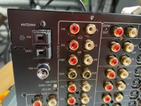
That's a great idea! However I only see 1 inductor near the antenna!
This is a picture from the internet not my unit.
Swap L522 and L523, ANT terminal 2 not used?.
That's a great idea! However I only see 1 inductor near the antenna!
This is a picture from the internet not my unit.
Last edited:
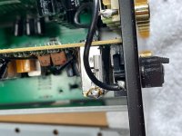
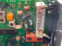
On the third photo, I guess the coax is the FM round plastic and the mini resistor has broke off between the corner of the silver box and the coax solder on the GND lug.
The AM gnd is a straight short, hence strong enough not to crack.
Movement of the chassis may have cracked the 'resistor'.
I would clean up the axial-less end of the 'resistor' and scrape away enough to solder a flexible short wire and resolder back to the original position. Any flex of the chassis wont crack your new solder joint.
I could not salvage that inductor. So I bought 3 different inductors at mouser. all with 10uh but different amps. Do amps matter? Does resonance matter?
PS: I thought it was an inductor not a resistor
PS: I thought it was an inductor not a resistor
The inductor is a filter of some sort on the grounding end of the FM socket.
Amps does not matter as it is GND to GND. Try all inductors including a shorted wire in the circuit and listen to the best and weakest FM stations. If no noticeable difference then, Bob is your uncle.
Amps does not matter as it is GND to GND. Try all inductors including a shorted wire in the circuit and listen to the best and weakest FM stations. If no noticeable difference then, Bob is your uncle.
Last edited:
Thanks for that idea. Great idea if I was 20 years younger. Wish I could physically do that but: Soldering in the garage. Unit must weigh 40-50 lbs. I would have to lug it upstairs after and reconnect everthing and then disconnect and repeat. I just picked the inductor with highest Q value even though I have no clue what that means. Nowhere on the web could I find a "two band" component that looked like the original inductor or resistor. One place I read was if there are only two bands (ie no multiplier) the it becomes the value x 10 to the 0 power and thats how I picked 10 uh. Hopefully its not a resistor.
- Home
- Design & Build
- Parts
- Resistor or inductor Two bands