Hi, I was wondering if someone can help. I'm looking at a schematic and for a Teac 500 amp. The pre amp section is confusing me. It has a 1.8k resistor but says at the bottom that the value could change with performance. It has been on my mind for a few months now and I'm just trying to understand what it actually does and how it could affect the sound. I have circled it in red. Thanks
Attachments
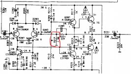
The pre amp section is confusing me. It has a 1.8k resistor but says at the bottom that the value could change with performance.
That resistor is vey important, it sets the amplifier's closed loop gain, along with the 22k resistor.
I don't know why they would say that. Maybe they mean that the capacitor C209 could change, instead.
Last edited:
Hi Rayma, what does that mean? you mean how loud the preamp is? The asterisk is next to the resistor. I did do a measure months back and the value of the resistor actually used was higher than the 1.8k. I kind of recall 2.2k. I still have the amp so I can check but I'm 99% certain those are the values. The reason I checked that in the first place is because it has an asterisk next to it and it bothered me for months as I was also looking to replace some old caps. Thanks
Hi Rayma, what does that mean? you mean how loud the preamp is?
Yes, the gain or loudness you get for a given volume control setting.
That is odd, normally those two resistors are fixed in value.
So less i.e 1.8k is louder than 2.2k?
The formula is gain = (1 + 22k/2.2k) = 11 times, or 21dB with the 2.2k resistor.
With the 1.8k resistor instead, the gain = (1 + 22k/1.8k) = 13 times, or 22.4dB.
So there's only 1.4dB more gain with the 1.8k, not much.
Can I be your apprentice? How do you even know this stuff?
OK serious talk what you recommend? Is louder better or not? They did use higher value than schematic
OK serious talk what you recommend? Is louder better or not? They did use higher value than schematic
Is louder better or not? They did use higher value than schematic
Either value is ok, since the gain difference is very minor.
Maybe they made a bunch with the wrong value, and this is their way of making it legitimate, since the change is fairly minor?
Maybe they made a bunch with the wrong value, and this is their way of making it legitimate,
since the change is fairly minor?
Actually I suspect that they are tweaking the high frequency response that way, instead of the more
proper (but more difficult and expensive) way of varying the phase lead capacitor across the 22k.
So would I get more treble if I used 1.8k instead of 2.2k? I thought It just made it louder. Thanks
So would I get more treble if I used 1.8k instead of 2.2k? I thought It just made it louder.
This would not make any audible treble change, but is in the MHz region only,
and has to do with circuit stability.
OK. Thanks for that. Was bothering me for months!!
It should have, it bothers me too.
You can think of this type of amplifier as a discrete opamp. The bases of the two transistors in the input stage, Q201 & Q203, are the non-inverting and inverting inputs. The resistors in question form the negative feedback voltage divider, shown here as Rf and Rg

You can read more about this here:
Operational amplifier - Wikipedia
You can read more about this here:
Operational amplifier - Wikipedia
Last edited:
The diagram kind of makes sense although the Vout on the schematic does not connect to - on the transistor. That's what I'm saying that just doesn't match up and confusion sets in 🙁
Really love this stuff need lessons!
Really love this stuff need lessons!
Really love this stuff need lessons!
https://people.ece.cornell.edu/land/courses/ece4760/ideas/singlesupply.pdf
Q203 base IS the "-" input in that discrete Op Amp.The diagram kind of makes sense although the Vout on the schematic does not connect to - on the transistor. That's what I'm saying that just doesn't match up and confusion sets in 🙁
Really love this stuff need lessons!
Same way as Q201 base is the "+" input , as shown in the example Op Amp schematic shown.
Thanks for the link but looking at it makes my eyes go blurry!
Rayma can I ask did you study this? If so for how long until you were able to understand this fully?
JMFahey so is it connected via the diode d207 and resistor r211?
Rayma can I ask did you study this? If so for how long until you were able to understand this fully?
JMFahey so is it connected via the diode d207 and resistor r211?
Rayma can I ask did you study this? If so for how long until you were able to understand this fully?
I'm an electrical engineer, so maybe around 7 years all together.
- Status
- Not open for further replies.
- Home
- Amplifiers
- Solid State
- Resistor in preamp audio path. Purpose?