Hello,
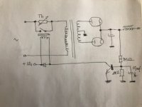
I have to change (eliminate) a delay circuit of a B+ supply for a simple resistor with a manual switch. The delay is not working properly and I have tried already to start up the amp with two 50W 100 ohm resistors in series, switching it off the line after a few seconds. Sound quality is way better than with the delay circuit in the system. The resistor is between the 220V AC line and the primary of the B+ transformer, which has a secondary with 630V/250mA-0-630V/250mA. It is used with a full wave tube rectification, with two 5R4WGY tubes. It has a choke input that makes the PS draw a very large load when it starts up, which is too much for the tubes, hence the need for a soft start.
I would leave it like this if it was not for one thing: if I don't switch the resistor off the circuit it gets very hot. I can't recall how to calculate the needed rating power of the resistor. The 200 ohm resistance seems to do a perfect job for a soft start after about 10 seconds. Can someone help?
Thanks!
Thank you, already tried that. Doesn't work in this case. Besides, the thermistor remains in the line and harms the SQ.
Can you help with the power calculation? I know it's basic stuff, but I'm not getting it.
Can you help with the power calculation? I know it's basic stuff, but I'm not getting it.
Where are you putting the resistor. In the primary or secondary circuit? Can you measure with a multimeter the current at switch on and after 10 seconds. You can calculate the necessary resistor power using P=I*I*R. Where P is in watts, I is in Amps and R is in Ohms. Do two calculations. 1 at switch on and 2 after 10 seconds. If it's not to big go for the 1st calculation. If P is very large set somewhere between the two.
Funny today I've just used a thermistor for that exact reason, to make the startup with 2 parallel GZ34 choke input softer on them, as I wanted to add much more filter caps.
I choose a 200 ohm 1A thermistor with the first film cap 50uF after the choke, then the rest of the PS. It works perfectly.
I choose a 200 ohm 1A thermistor with the first film cap 50uF after the choke, then the rest of the PS. It works perfectly.
Where are you putting the resistor. In the primary or secondary circuit? Can you measure with a multimeter the current at switch on and after 10 seconds. You can calculate the necessary resistor power using P=I*I*R. Where P is in watts, I is in Amps and R is in Ohms. Do two calculations. 1 at switch on and 2 after 10 seconds. If it's not to big go for the 1st calculation. If P is very large set somewhere between the two.
On the primary.
you mean P=I*R, correct? I believe you have mistyped P=I*I*R.
Funny today I've just used a thermistor for that exact reason, to make the startup with 2 parallel GZ34 choke input softer on them, as I wanted to add much more filter caps.
I choose a 200 ohm 1A thermistor with the first film cap 50uF after the choke, then the rest of the PS. It works perfectly.
My cap after the choke is 450uF.
Where are you putting the resistor. In the primary or secondary circuit? Can you measure with a multimeter the current at switch on and after 10 seconds. You can calculate the necessary resistor power using P=I*I*R. Where P is in watts, I is in Amps and R is in Ohms. Do two calculations. 1 at switch on and 2 after 10 seconds. If it's not to big go for the 1st calculation. If P is very large set somewhere between the two.
In my present situation, there's no way I can measure those currents.
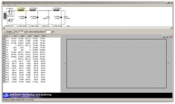
Here's a simulation of the PS I have done in the past. I believe it is accurate, let me know if you can estimate things with it.
Attachments
.... two 50W 100 ohm resistors in series, ... 220V AC line ... gets very hot. I can't recall how to calculate the needed rating power of the resistor. ..........
Worst case: the amp stays a dead-short, you have 220V^2/200r or 242 Watts steady heat.
Some rough pencil-work suggests that you are really just bring B+ part-way to final value, and when you cut-out the series resistors there is *still* a large surge. I think you want a streetcar tram motor controller with several steps between Start and Run.
To be more complicated: you could find an old 110V relay, plus a series resistor, so it won't pull-in until near 90% of final voltage. However 110V relays are often not rated for high voltage on contacts. And I know better than to use offensive language like "MOSFET".
Hi, it's typed correctly. I is squared. To write another way: P=I^2 * R
Your simulation displays the secondary currents and the theoretical load, not the actual current through the primary which is why I want you to measure it. (Although they can be calculated backwards). Get yourself a low cost DVMM and measure. It will lead to a better outcome on the selection of power rating for the resistor.
Your simulation displays the secondary currents and the theoretical load, not the actual current through the primary which is why I want you to measure it. (Although they can be calculated backwards). Get yourself a low cost DVMM and measure. It will lead to a better outcome on the selection of power rating for the resistor.
On the primary.
you mean P=I*R, correct? I believe you have mistyped P=I*I*R.
Worst case: the amp stays a dead-short, you have 220V^2/200r or 242 Watts steady heat.
Some rough pencil-work suggests that you are really just bring B+ part-way to final value, and when you cut-out the series resistors there is *still* a large surge. I think you want a streetcar tram motor controller with several steps between Start and Run.
To be more complicated: you could find an old 110V relay, plus a series resistor, so it won't pull-in until near 90% of final voltage. However 110V relays are often not rated for high voltage on contacts. And I know better than to use offensive language like "MOSFET".
This last idea is the best.
Using the NO contacts either side of the current limiter (Resistor PTC whatever).
When the coil voltage approaches a fraction of its rating, it will close. The exact close voltage will have to be found experimentally (easy if you have a variac and DMM)
If you're switching on the HT DC side, then wire 2 or more NO contacts in series, so they have a better chance of breaking the DC arc.
Or rather making the contact, without contact arcing, and then breaking it, upon power down and discharge of the PSU, without contact welding from arcing on the Break
Last edited:
My cap after the choke is 450uF.
I see. My choke is not that good as the rectifier started to arc if I added over 250uF after it.
The thermistor allowed me to do so.
Yours seems excellent.
Hi, it's typed correctly. I is squared. To write another way: P=I^2 * R
Your simulation displays the secondary currents and the theoretical load, not the actual current through the primary which is why I want you to measure it. (Although they can be calculated backwards). Get yourself a low cost DVMM and measure. It will lead to a better outcome on the selection of power rating for the resistor.
Thank you. I have a DVMM, that's not the issue. I would like to have a ballpark figure before I re-assemble the amp (that's why I can't measure it yet). Since the supply weights a ton and I have a weak back, I was hoping to have an approximative yet safe figure and go with that.
- Home
- Amplifiers
- Tubes / Valves
- Resistor for B+ soft start

