Hi guys, this may be a silly question... i tried google around but i couldn't find an answer.
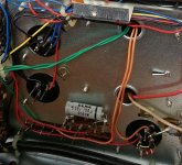
Can someone tell me what the resistor between the two leads of the capacitor is for? (The one on the lower right corner in the pic).
The ampli is a SS Kenwood ka4004.
Thanks!!
Can someone tell me what the resistor between the two leads of the capacitor is for? (The one on the lower right corner in the pic).
The ampli is a SS Kenwood ka4004.
Thanks!!
Attachments
What is its function?
I tried disconnecting that resistor and it seems to me that the ampli is sounding same as before.
I tried disconnecting that resistor and it seems to me that the ampli is sounding same as before.
Tha cap has three legs but two of them are connected together (on the negative). So basically it seems like the resistor is "shorting" pos and neg.
What is its function?
That resistor is from the output of an emitter follower voltage filter circuit to ground.
Hard to say what it's supposed to do in that kludge of a half wave rectifier circuit.
I downloaded the schematic from Elektrotanya, and it appears to be C2, lower left corner of main schematic. It calls it a single section 1000uf 63v cap. I don't see the resistor.
I don't see the resistor.
It's off the pcb, to the left of it on the schematic.
I didn't noticed it either on the schematic... thanks for your answers everyone!
I'm still wondering how a capacitor can works if it's shorted... or putting a resistor is different then putting a wire?
I'm still wondering how a capacitor can works if it's shorted... or putting a resistor is different then putting a wire?
Resistors and wires differ in resistance and cost. That is why most circuits use some suitable combination of resistors and wires. Resistors are used when a particular resistance is needed. Wires are used when a particularly low (but otherwise unspecified) resistance is needed.
Uh, yeah.
But to partially answer the original question, I have seen drain, or bleed resistance added to capacitors in an effort to further dampen the circuit. A typical value on a dac power pin would be 1 meg for example.
I did not look at your circuit, but if there is a regulator involved, the dampening may be a desired effect.
A 1 meg resistor added to most solid-state circuits would do one of two things:phase said:A typical value on a dac power pin would be 1 meg for example.
1. nothing
2. stop the circuit from working
Can´t se what leg is what in that multn section cap, but that 900 ohm resistor can do one o0f 2 things, both useful to what the cirrcuit designer wanted to acheve.
1) if the resistor goes from positive to positive, it´sprobably part of a CRC supply filter circuit, it being the "R" part.
Google CRC supply filter to understand what it does.
2) if from positive to ground, it´s a bleeder resistor, it ensures than when amp is turned off, it discharges to 0V in a reasonable amout of time, usually minutes or less.
In this latter case, it might have been added at the assembly stage if they found it desirable, and not necessarily back annotted to original printed schematic. No big deal.
Many schematics include the "we reserve the right to modify it at any moment" label.
Thanks everyone for your answers.
The resistor is from positive to negative, which is grounded to the case.
Visually, it looks like an "aftermarket" job but, as rayma noticed, the resistor is the schematic so I think that the right answer may be point 2) by JMFahey: that would explain why the ampli works exactly the same when I tried removing it.
- Status
- Not open for further replies.
- Home
- Design & Build
- Construction Tips
- Resistance between cap leads