Hi everyone!
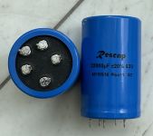
I'm searching for the datasheet of a seemingly rather "exotic" (and old?) electrolytic capacitor marked with "Rescap 22000µF +/-20% 63V 40/105/56 Plus=1 XD". Here's a picture:

I do see that Pin1 is "+", but have ALL other pins to be connected to "-"? Or are there n/c pins as well? I'd be greatful for explaining information, especially about the connection pin out or best case a datasheet.
Thanks a lot folks!
Winfried
I'm searching for the datasheet of a seemingly rather "exotic" (and old?) electrolytic capacitor marked with "Rescap 22000µF +/-20% 63V 40/105/56 Plus=1 XD". Here's a picture:
I do see that Pin1 is "+", but have ALL other pins to be connected to "-"? Or are there n/c pins as well? I'd be greatful for explaining information, especially about the connection pin out or best case a datasheet.
Thanks a lot folks!
Winfried
Attachments
Usually all of the pins not documented are not connected. In this case the # terminal is (-), terminal 1 is (+) and terminals 2, 3 & 4 unlikely to be connected, but there for mechanical integrity. It's easy enough to check for continuity to be sure.
Hi John,
thanks for your quick answer! The upper left pin is marked "-" which is probably the one you mean with "#". So, we're talking pin no. 2, 3, 4 to clarify.
I've tried to measure for continuity with an Ohm-Meter and found that the pins 2,3,4 show strange behavior:
When measuring pins 2, 3, 4 from the + or - pins the Ohmmeter shows 3-5 MOhm, but constantly, slowly rising values with time.
Measured Capacitance shows 21mF from + to - and measuring 2, 3, 4, to + or - shows between 0.5 µF and 3µF.
Any explanation for this behavior?
Would it be safe to not connect 2, 3, 4 or is their connection to "-" required?
(I'm asking because a potentially necessary unsoldering would be much easier if only + and - were soldered/connected).
Thanks again!
Winfried
2,3,4 are connected to SOMETHING inside, so they farm a capacitance, wwhich your meter shows as a charging.
It is just a cap, it won't need some arcane weird connections. Hook up the + and - terminals. The other three can have a place to solder, but until I see a data sheet I wouldn't make electrical connections to them.
It is just a cap, it won't need some arcane weird connections. Hook up the + and - terminals. The other three can have a place to solder, but until I see a data sheet I wouldn't make electrical connections to them.
The extra terminals are there to anchor the capacitor so that it can survive vibration tests which will be part of its specification. Large components can be subjected to significant forces when used in industrial applications and those forces can cause premature failure. If the component is n't anchored properly it may resonate (mechanically) and amplify the vibrations to the detriment of the component.
The standard practice is to solder the extra anchor pins to pads on the circuit board, but in the absence of advice to the contrary not to connect them to any other part of the circuit because their electrical status is indeterminate, i.e. they are not guaranteed to be connected to, or insulated from, some part of the capacitor or can.
Below is a link to a spec sheet from EPCOS that explains the extra pins. The circuit information is specific to EPCOS components but gives a general idea of the use of the extra pins.
https://www.tme.eu/Document/68d3ed0ac24f115feb88beaf1c8ef125/B43510_B43520.pdf
Last edited:
Thanks for the clear directions Enzo and John!,
I don‘t have and could not find a datasheet, that‘s why I starten the Thread 😉
Greetings,
Winfried
I don‘t have and could not find a datasheet, that‘s why I starten the Thread 😉
Greetings,
Winfried
Maybe it's like this;
Between pin 1 and pin 2 4000uF
Between pin 1 and pin 3 10500uF
Between pin 1 and pin 4 5600uF
pin with dots markings only for support.
Try to measure the RC time with these combinations.
Just an idea.
Greetings from Simon
Between pin 1 and pin 2 4000uF
Between pin 1 and pin 3 10500uF
Between pin 1 and pin 4 5600uF
pin with dots markings only for support.
Try to measure the RC time with these combinations.
Just an idea.
Greetings from Simon
- Home
- Design & Build
- Parts
- Rescap Electrolytic pin-out/connection