R648 and R650 are good. In fact, I replaced them even though they tested good. My very first thought was that they were not dropping the voltage enough.
I will try to take some new measurements tonight after work. I will measure the dc offset in front of the circuit breaker. I see your point, the breaker could be flakey.
The right channel was still playing music before I started working on it. It was just distorted sounding compared to the left. If the output transistors were "blown", would there still be sound coming out of that channel?
Replacing parts without data injects more problems. I make about 20% bad solder joints the first try and I've been doing this 56 years. I do check my work afterwards with the dvm ohms scale from lead I soldered to the next component.
Do you have a DVM? You can check the output transistors with power off & mains caps discharged in 2 minutes on diode scale, in place. If no diode scale, use the 2000 ohms scale. b-e and b-c forwards 450 to 700 mv diode scale (ohms on that scale) backwards a much larger number. Forwards is red lead on p, black lead on n.
Reason for focus on output transistors, 90% of problems at repair shops are that. Especially on amps used by amateur & bar bands. Wiring problems blow OTs. The 20 year old amp that goes wimpy or distorted in a living room gradually, less often cause is OTs.
As far as the bad noises, transistors can be leaky instead of blown. Also diodes.
If these negative voltages go away as you are playing music, as you said, you may have to make DC tests with music running through the amp. If load (speaker) makes wrong voltages go away, attach a trash speaker (blocked by series back to back 2200 uf caps to protect against DC on speaker). No sense tracing AC signals until the DC voltages match the schematic. In the extreme case, you have to find the first place signal music/sine wave is distorted, with a scope or sound probe. Slow & unrewarding, finding DC voltage problems points out problems quicker.
Last edited:
Well, I am sure that you guys already know by now, I have a lot to learn.
I sat down tonight with a fresh set of eyes. I did confirm that, in spite of having -12V and -13V at the bases of the right channel output transistors, the dc offset was in fact 0.
I took some fresh DVM measurements on the output transistors. The right channel 2955 with positive to collector and negative to base showed 540. Then positive to emitter and negative to base initially seemed OK but then the value just kept increasing. I checked the left channel and positive to collector and negative to base was 545 and positive to emitter and negative to base was 553.
The two 3055 seemed fine.
I pulled the right channel 2955 and it was bad. I pulled a 2955 out of the other unit, a NAD 3130, and checked that it was good. (the 3130 is a similar design with no emitter or base resistors). I cleaned everything up well and put fresh heatsink compound and installed. Immediately, voltage on right channel is now correct. I hooked the scope up and output looks good.
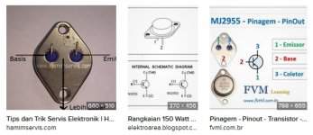
So it seems that a bad MJ2955 was the problem all along. What is strange is that the service manual shows the pinout of the 3055/2955 incorrectly. (see diagram). Maybe that is why i didn't pick up the problem with the transistor initially, I don't know.
I haven't listened to it yet but it appears the problem is solved.
I really want to thank you guys for helping with this. Yes i made a simple problem very difficult. You all definitely pointed me in the right direction and I feel that i did learn a lot from this. It seems that for every one thing I learn, I discover that there are 50 other things I don't understand.
Now, if I want to replace the 2955 in the 3130, you say that i can't use a modern 2955, is that correct?
I sat down tonight with a fresh set of eyes. I did confirm that, in spite of having -12V and -13V at the bases of the right channel output transistors, the dc offset was in fact 0.
I took some fresh DVM measurements on the output transistors. The right channel 2955 with positive to collector and negative to base showed 540. Then positive to emitter and negative to base initially seemed OK but then the value just kept increasing. I checked the left channel and positive to collector and negative to base was 545 and positive to emitter and negative to base was 553.
The two 3055 seemed fine.
I pulled the right channel 2955 and it was bad. I pulled a 2955 out of the other unit, a NAD 3130, and checked that it was good. (the 3130 is a similar design with no emitter or base resistors). I cleaned everything up well and put fresh heatsink compound and installed. Immediately, voltage on right channel is now correct. I hooked the scope up and output looks good.
So it seems that a bad MJ2955 was the problem all along. What is strange is that the service manual shows the pinout of the 3055/2955 incorrectly. (see diagram). Maybe that is why i didn't pick up the problem with the transistor initially, I don't know.
I haven't listened to it yet but it appears the problem is solved.
I really want to thank you guys for helping with this. Yes i made a simple problem very difficult. You all definitely pointed me in the right direction and I feel that i did learn a lot from this. It seems that for every one thing I learn, I discover that there are 50 other things I don't understand.
Now, if I want to replace the 2955 in the 3130, you say that i can't use a modern 2955, is that correct?
Attachments

Last edited:
Confusing it is indeed!
Just goes to show you that you can't always rely on other's information.
Oh, the internet, don't ya love it? 🙄
You'll have to use modern epitaxial MJ2955, or something better like MJ15016. There are no homotaxial MJ2955 left anywhere. Last made about 1980 by Motorola, a few tiny or east european suppliers kept on a few more years. Marking "h" was not universal even by RCA & Motorola.Now, if I want to replace the 2955 in the 3130, you say that i can't use a modern 2955, is that correct?
What you have to do is insert a resistor between emitter & centerline (circuit breaker) to prevent thermal runaway. Typically .33 ohms 3 to 5 watt, although .47 to .51 ohms is used in amp brands known for not blowing up. I would suggest acquiring a pin vise and a #45 drill. Cut the PCB lead, drill a hole through the board with the drill on the driver side of the gap next to the lead. One lead wraps around E of Q618, other goes through hole and bends over to cross lead to Q614. Solder there. If board has coating over the pcb leads, has to be scraped off for solder to stick. Resistor can stand up to save space.
ST semi says max diameter to MJ2955 lead is 1.15 mm, you want bigger than that.
Sorry about misdirection to C630 & C624. What the pro shop practices say about always replacing the output transistors before doing much diagnosis proved right in this case.
Yes that NAD drawing of TO3 case is rather bad. Can't tell which end is the long direction from the holes. Base is the left lead on the bottom looking from the long direction.
Don't forget to renew the mica washer; life is about 30 years. Heat sink compound (non-silver containing) required for mica, or modern silicon rubber insulators don't require the compound.
Last edited:
Regarding the C630 C624 thing, no apologies necessary indianajo. We had to look at all possibilities.
I will do the bias adjustment on the 3020 tomorrow. Looks pretty straight forward.
My friend wasn't too concerned about the fate of the NAD 3130. He didn't think it was anything special so I may just keep it as a parts unit OR it may be fun to change out the output transistors and try the emitter resistor mod. If I do, I may come to you for some help/advice.
Thanks again to everyone who offered advice.
- Home
- Amplifiers
- Solid State
- Requesting help repairing NAD 3020 series 20