The corners made it easier to see if he changes in volume are conical, parabolic or exponential. After doing this I determined I should set l12 as Con, L23 as Par and L34 as Exp. Not sure if this is what people do to figure it out.
Hmm, with straight dividers and a parallel walls, I don't see how any of them can be anything but parabolic except possibly the last bend, which as Oliver noted should be simmed in two sections.
GM
Hi 16gnomes,
As to power: use Hornresp to calculate SPL, and go to Tools/Sample. There you can type in the frequency you are interested in (in the slider), and it will return (among other values) the actual power.
P = E x I is correct, but a dynamic loudspeaker is a peculiar load w/ almost constantly changing phase angle (type into google: "voltage and current cosine phase angle Wuidart" for a short explanation of phase angle).
1.88 Ohm is already the result of two coils in parallel, so for one speaker you don't have to double it again; I'm assuming, that in the JBL technical data sheet the 1.88 indicates the test/measurement conditions for the T/S parameters, i.e.: both coils in parallel.
Regards,
Just another thought.
Hi 16gnomes,
I'd like to redirect your attention for a moment to bjorno's design in Post #2. A very similar method can be applied to the JBL GTO1014s, and it would result in a relatively easy to build enclosure. By keeping the cross-section equal throughout the path you end up with, e.g.: a dual driver tapped quarter-wave pipe (T-QWP). An easy build w/ only right hand corners. I'll attach two Hornresp Export file examples. SPL is not everything. 🙂 These examples will stay below Prms, and just reach Xmax (when viewed w/ stuffing and active bandpass filter). You can easily modulate the response by changing the dimensions. There are a few examples of threads where bjorno's method has resulted in happy builders. Maybe just grap some cheap wood and start building some proof-of-concept box?
Regards,
Attachments
Hi Y'all,
Just a quick link to the lowest price for the JBL GTO1014D that I've seen sofar:
JBL GTO1014D 10" 1400W Dual 4-Ohm Subwoofer at Onlinecarstereo.com
Regards,
Just a quick link to the lowest price for the JBL GTO1014D that I've seen sofar:
JBL GTO1014D 10" 1400W Dual 4-Ohm Subwoofer at Onlinecarstereo.com
Regards,
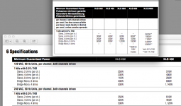
1) Assuming you mean the Crown XLS402 (I could not find specs for a "Crown402D") it is rated for 300 watts at 8, 450 at 4 ohms.1)Abbreviating the amp I mentioned sometime earlier. The Crown 402D.
I'll say Crown from this point on for those dropping into the conversation late.
2) I guess they consider each of these coils 4ohm?
3)Ok but why? I want to know! 🙂
2) Correct, which leaves out the 2 ohm option, as the Crown XLS402 is not rated for two ohm operation. It can be bridged mono in to 8 ohms for 900 watts.
3) A Con(ical) expansion using straight horn walls requires expansion in both vertical and horizontal dimensions.
Since most build TH with two parallel walls and flat horn sections, but Hornresp models the horn as round, Par (abolic) (kind of the inverse of exponential) approximates the expansion properly.
In the real world, most bass horns are put together with parabolic sections that in series approximate something like a conical, exponential, or hypex (exponential/hyperbolic) expansion.
Art
Art, I do believe my values and my terminology are correct. The 402D is the latest version of the Crown 402, and the manual cites the lowest impedance at 2 ohms a channel or 4 ohms bridged. There are no other amplifiers on the market with "402" at the end, so of course it's an XLS! I'm getting the feeling you're more interested in giving me a hard time than helping at this point. I'm sorry I don't know as much as you. I'm sorry if it annoys you I'm not understanding some of the things you're saying, but I am trying! I'm here to learn! I'm a novice! PLEASE understand that. Amplifiers aside, I'd really like to focus 100% on the box. If it turns out one particular amp doesn't fit the bill, I'll find something else, that's not an issue right now. How much power it requires or any additional signal filtering is something I can get into after the box is designed. Size and shape are what all of my energy and thought is going into. I'm here because I want to know how to Do It Myself and I know I have a long way to go.
TB46- I really wish there were words more powerful than: Thank you!
I did say earlier that I have no doubt bjorno provided me exactly what I asked for. Problem is, I don't know what all his numbers mean or why it works so well. Let me back up for a moment and say: the reason I'm trying to D-I-Y is so I can learn. And yes, I know absolutely SPL isn't everything. Very few people run their systems at full power all the time, in fact, I don't think I ever have pushed one of my systems to it's absolute limit. However, max performance information is useful for matching components and getting an idea of how hard the system is being pushed from external measurements. I always carry a SPL meter so I'd know if I'm, for instance, at 120db a box that shouldn't do better than 122 is pretty close to its limit and I better make sure the limiter is kicking in by then so I don't damage anything. I've never blown anything, speakers, amps or otherwise and I'm not planning on breaking that record any time soon.
Few more questions:
1) How do I add a section after S4? Make a TH1 as you say. I've been looking around both in hornresp and the net and can't seem to find how I'd do it.
2) I noticed bjorno has filters and several posts in this thread to me refer to filters. May I have a brief explanation or a link that explains why I would want to use them in hornresp?
More thoughts on the expansion rate Con, Exp, Par. I thought it meant the rate of volumetric expansion rather than how the horn looks in 2D. Given, a parabolic graph expands quickly at first then the rate of expansion slowly decreases, an exponential graph is the opposite, it rises slowly than the rate of expansion increases, well exponentially. Conical is totally linear. I'm imagining each section as if it was 3D filled with water. When I graph my measured increases in volume across all sections, as my previous post shows. You can see a 100% linear increase in volume from S1 to S2, S2 to S3 it is parabolic S3 to S4 it is exponential. Even if each section is a straight board, the average increase in volume across all sections is not the same as two straight boards would be with no bends. This is my logic when choosing these values. You can make a parabola out of multiple sections of straight boards. Put enough sections of straight board together in a parabolic shape and it looks like a parabola from a distance. That's all I'm saying. The hornresp schematic appears to be representing a side 2D view of a 3D modeled horn, therefore, the increase in volume as I've measured should match the sim (in my novice eyes).
Of course I'll do what you guys say I should, I'm just not understanding how my above logic is faulty. My method will provide a more accurate means of determining total volume since I'm modeling the increase in volume from my actual measurements. I've noticed from playing with the values that they don't make a massive difference in response, but I still want to know why you guys are saying this.
I have a degree in physical science, I took calculus, I can handle math and calculations with Excel just fine. If I'm doing it wrong or not understanding the fundamentals here, I want to know why specifically.
I had not heard of the XLS series of Crowns before, they have had added a lot of different lines in recent years. The Crown XLS 402 link I found had a different specification than the one you listed, the "D" must have improved heat sinks (or something) to allow 2 ohm rating.Art, I do believe my values and my terminology are correct. The 402D is the latest version of the Crown 402, and the manual cites the lowest impedance at 2 ohms a channel or 4 ohms bridged.
Attachments
Hi 16gnomes,
Post #87:
to Question 1: In the Hornresp Input window double click on the TH to the left of the driver arrangement field (below Re). If you keep on double clicking you'll go through the different driver arrangements.
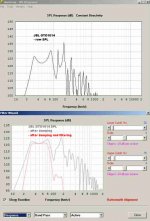
to Question 2: Let's say you spend long hours on arriving at a beautiful ruler-flat SPL curve for an enclosure, but in the actual build you'll be adding acoustically absorbent lining or stuffing, and you'll be using a low cut (high pass) filter to prevent excessive driver excursion below the desired design window, and a high cut (low pass) @ the upper end of the passband. What will happen to your SPL curve? Right, so it is really nice to be able to apply lossyness in the Speaker Wizard, store the result in Memory, and go over the the Filter Wizard, and apply your desired filters. You may even want to go back and forth a few times, and intentionally introduce non-linearities in the Speaker Wizard, so that your overall response after the Filter Wizard becomes whatever you are looking for; e.g.: for in room response a flat response may not be what you need, it may be better to have a slightly rising response. It's just great that David McBean was able to add these functionalities into Hornresp.
As to the flare rates, there was a discussion in the Collaborative Thread that went into the details. The parabolic comes from the fact, that when you take two straight boards and build an expanding section between two parallel boards the rate will be parabolic. Now, once you use more boards, different angles, non parallel boards it could be anything (also what Art said in #85 above).
Regards,
Post #87:
to Question 1: In the Hornresp Input window double click on the TH to the left of the driver arrangement field (below Re). If you keep on double clicking you'll go through the different driver arrangements.
to Question 2: Let's say you spend long hours on arriving at a beautiful ruler-flat SPL curve for an enclosure, but in the actual build you'll be adding acoustically absorbent lining or stuffing, and you'll be using a low cut (high pass) filter to prevent excessive driver excursion below the desired design window, and a high cut (low pass) @ the upper end of the passband. What will happen to your SPL curve? Right, so it is really nice to be able to apply lossyness in the Speaker Wizard, store the result in Memory, and go over the the Filter Wizard, and apply your desired filters. You may even want to go back and forth a few times, and intentionally introduce non-linearities in the Speaker Wizard, so that your overall response after the Filter Wizard becomes whatever you are looking for; e.g.: for in room response a flat response may not be what you need, it may be better to have a slightly rising response. It's just great that David McBean was able to add these functionalities into Hornresp.
As to the flare rates, there was a discussion in the Collaborative Thread that went into the details. The parabolic comes from the fact, that when you take two straight boards and build an expanding section between two parallel boards the rate will be parabolic. Now, once you use more boards, different angles, non parallel boards it could be anything (also what Art said in #85 above).
Regards,
Last edited:
Flare rate - Expansion
Hi 16gnomes,
Here are two quotes I found in:
http://www.diyaudio.com/forums/subw...ped-horn-project.html?perpage=25&pagenumber=1
Sabbelbacke, Post #1322: "Keep in mind that flare rate is the expansion of the radius, not area."
Sabbelbacke, Post #1328: "...see Post...(and surrounding discussion)..."
Hope this helps,
Regards,
Hi 16gnomes,
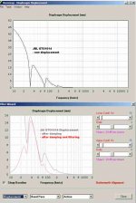
Just in case you don't suffer from a case of data overload yet: I quickly moved the sliders around, and changed the TQWP into a TH, it won't go quite as low, but it will be a lot louder. It's also an interesting case to look at the SPL, first raw from the Input screen then w/ partial stuffing in the Speaker Wizard, and finally in the Filter Wizard. Also take note, how the stuffing and filtering affects the driver displacement. I'm sure that this can be improved in the details, but it's a start.
Regards,
Attachments
Pardon my delay, very busy.
Art, thank you for taking that gracefully. I should have given you the benefit of the doubt. After I wrote I found another (newer) manual that doesn't list the 2ohm stereo rating. It's actually the older documentation that shows the low impedance specs. Not sure why that is. Anyhow I figured I'd be wise to go by the amp's power supply which says 625w, printed right on the back. Since the old manual shows a total 2ohm stereo max current draw of 10A at 50% duty cycle, this leads me to believe I shouldn't bet on getting anything above 40V if bridged into 4ohms, or about 400w. I really wasn't planning on dropping the resistance that far anyway but now I'm even more convinced. At an ideal 8ohms bridged, I should be able to get a full 625w and 70V. However, considering the two voice coils of the GTO in series provide a min impedance of only 3.76ohms, I can't consider that realistic either. Until I started talking to you guys I would have considered the two coils in series to be 8 ohms, but now it's looking like my true voltage maximum for this amp, in this configuration, should actually be somewhere between 30 and 35v. Does that sound right?
^ I'm actually very glad you brought this up Art. You've shattered my brain once again and I'm incredibly grateful this illusion is now destroyed.
TB - Really appreciate the replies. Yes, lots of info and I haven't had time to read all that yet, but I will over the next couple days. Before my previous post I saw people saying "double click TH" but in my ignorance I assumed they meant the box, not the actual red TH symbol (had no idea you could click that), face-palmed that one. So after adjusting the values in a TH1 config, I honestly cannot visibly tell the difference in my response graphs so the change must have been very minor.
Also very much appreciate the explanation of the filters in hornresp. The reason I asked is so I could input bjorno's numbers (minus the filters) and use that response and phase graph to compare with the boxes I've designed since I really have no gauge of what's good in terms of these outputs. This will hopefully help me get a better idea of what I should be shooting for.
Regarding phase response, I know it's also important but not quite sure how important. My latest box looks pretty darn good (stays under +/-45) until above 70hz when it begins to rise sharply and spikes to +146 at 90hz. Should I be worried about that? I was planning on using a low pass no higher than 80hz anyway but it seems in this case I'd be wise to put it around 70hz to keep phase it in check. Is that right? When matching tops, should I shoot for them having a similar phase response at their crossover point?
Last question, in terms of response curves before adding filters, how much of a variation in response from peaks to valleys should I permit within my desired dynamic rage? I read in another post that people were putting inductors inline with the speaker to flatten out response. Is that something I should consider? I kind of like the idea of running raw box simulations without filters so I begin to understand what a good curve looks like. Do you feel that is a reasonable way for me to proceed? Or should I be including filters from the get go? I guess I could answer that question myself by looking at the response graphs of the boxes you've linked and studying them, but I'm curious if there is a general rule of thumb in that respect?
Boy, lots of work ahead, but loving every minute of it. Truly.
Last edited:
a curve doesnt mean much until you put a filter on it.
Go ahead and look at the spl from the non filtered response, but ALWAYS check with a filter, as this will help you gauge how much voltage is needed to reach xmax, and the final resp shape after you've applied the necessary means to stay within xmax. 9/10 I always find my tapped horns *sims* run out of excursion Inside the pass band (the middle excursion peak). A hipass wont do much to knock that down.
shoot for flatter than +/-3 db within your intended passband for spl response, although thats a good starting point.
As far as phase, dont really bother with it *just yet*. A tapped horns phase response will inherently **** the bed slightly above its intended passband due to negative . interactions between the rear and forward taps
Does that sound right?
At a glance, no, and especially so since this version has no 2 ohm, bridged 4 ohm or dynamic headroom ratings and even though it will be able to handle these loads at some reduced power rating, I'm not going to speculate for obvious reasons.
GM
Formula
Sorry if this has been stated already but in Post #67 Art stated:
Voltage x Voltage/Impedance = Watts.
The inverse is also true, Watts x Impedance=square root of Voltage.
While P=V2/R
The inverse of that is SQRT(P*R)=V
NOT
P*R=SQRT(V)
I think what he meant was P*R=V*V
ie
Voltage=square root of (Watts x Impedance).
- Status
- Not open for further replies.
- Home
- Loudspeakers
- Subwoofers
- Requesting assistance designing an isobaric tapped horn