1) Look at your amp output specs at various impedance, and you will see the answer is "no".1)Amp didn't seem to break a sweat. Should behave the same at 2ohms a channel, no?
2)Does my previous design make sense? Does it look like I'm getting the hang of it?
2) Getting better, but your estimate of 42 watts from 18.3v is way off at the impedance minima, which you will notice in tapped horns is generally very close to the driver's DCR.
18.3 x 18.3=334.89/2.9=115 watts per driver.
The HP filter can be placed a few Hz below the where the lower excursion rises to Xmax.
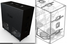
The drivers can also be placed "in line" with the horn path (as opposed to horizontal as you have done in the drawing) if you prefer a cabinet less than double the width of the drivers. If using an in line configuration, a "V" between the drivers may be useful, as can be seen in the DSL TH812 driver arrangement. The TH812 is two TH sharing a center wall, S1 is at the lower left and right of the cabinet. The drivers are arranged in two PP in-line pairs, with a horizontal twin.
The TH812 maximizes frontal area of the cabinet, large frontal area increases forward directivity, a cabinet like this can be 2-3 dB louder in front than the same horn using a small cabinet side for the mouth.
Art
Attachments
Hi 16gnomes,
Here is an example of a single fold TH using four drivers in a symmetrical layout, by littlemike. The same type box could be used for two drivers..... : http://www.diyaudio.com/forums/subwoofers/97674-collaborative-tapped-horn-project-299.html there are more pictures, and text on the next few pages of that thread (e.g.: 2996, 2997. 3004, 3017, 3021....).
Regards,
tb46, Hello! And thank you for the link. Much appreciated.
tinitus, thank you for those drawings! Definitely gives me some more sketchup fodder. It's good to see simplified designs that are basic enough for me to consider reasonably building.
Art, I love the TH812! That is actually the cabinet that made me fall in love with Danley. Of course, everything they make is pretty amazing. I'd cut off my left pinky toe to hear one of those, or really any of Danley's products (never have, no idea where the nearest one is setup). Anyway, again, your feedback is much appreciated regarding my incorrect assumptions about the 402. I don't understand the specs enough to calculate actual voltage, I just know I've run them at low impedance and had no problems or clipping lights. I just had a feeling bridging the 402 into two of these little Focals (in series) would be a bit much. If I ultimately have to do that, I would not bat an eye. I'm also very glad to hear my high pass can actually be a little lower - is that because most music doesn't contain frequencies below 33hz? Would it be any different if I was using pink noise? Are we talking 1-2hz or more? Maybe a better question is, how high can I let hornresp exceed xmax at 30hz in terms of percentage (100% being xmax). My most recent design posted shows xmax at 8mm (133%) at 30hz.
You know, a long time ago I thought I should use all of these Focals and try to build a TH812 with them but I wasn't confident with sketchup yet and I had a lot of other things going on, so I ultimately forgot about the idea. Do you know if there are any 2D representations of that cabinet? Plus I imagine I'd have to tweak it a little to get the most of my wimpy Focals.
Wait a minute. Epiphany! I could sell all of my Focals and buy Lab12s with a few bucks left over. The evil scientist in me is now very tempted to do so. Someone must have done this before?!?! I have no idea what Danley uses for drivers or how they compare to Lab12s.
I'm so amazingly glad I created this account. You guys rock ^_^
Last edited:
lol... the th812 would be blowing your 200 liter req out of the water.
I believe it uses the 12tbx100.
I believe it uses the 12tbx100.
I have no idea what Danley uses for drivers or how they compare to Lab12s.
His original TH [DTS20] uses it.
GM
1) Amp specs are usually given in watts at a specific impedance, 2, 4, 8, 16. Speakers are not a specific impedance, it varies widely with frequency.1)Anyway, again, your feedback is much appreciated regarding my incorrect assumptions about the 402. I don't understand the specs enough to calculate actual voltage, I just know I've run them at low impedance and had no problems or clipping lights.
2) I'm also very glad to hear my high pass can actually be a little lower - is that because most music doesn't contain frequencies below 33hz?
3)Would it be any different if I was using pink noise? Are we talking 1-2hz or more?
4)Maybe a better question is, how high can I let hornresp exceed xmax at 30hz in terms of percentage (100% being xmax). My most recent design posted shows xmax at 8mm (133%) at 30hz.
Voltage x Voltage/Impedance = Watts.
The inverse is also true, Watts x Impedance=square root of Voltage.
If you don't have a calculator with a square root function, hack away with best guesses until you hit the mark. Or use the Hornresp watt calculator.
2) No, it's because many speaker's suspensions become progressively stiffer the further they are pushed by the voice coil, and the voice coil progressively gets pushed less as it is further out of the magnetic gap. Notice there is no Xmax entry point in Hornresp- you can enter ridiculously high voltage and it will give impossible results, like speakers moving 200mm. Hornresp sims are not valid above Xmax, and some speakers Xmax (and other TS parameter) specifications are not correct.
Using filtered pink noise (like a 20-40 Hz BW24), experiment with your speakers open air, their excursion will be similar per applied power as in a TH or BR box driven below Fb. Using car or PA woofers you will generally find that excursion below Fb is far less than Hornresp predicts.
3) Pink noise contains all frequencies evenly distributed by octave for power, and has 12 dB dynamic range, though the pink noise used by speaker manufacturers is compressed to only 6 dB dynamic range. Some music ( Motorhead, Nickleback, etc.) is similar in frequency content and dynamic range to pink noise.
4) Start thinking in dB rather than percentages. Doubling (or halving) excursion requires a 6 dB change in power.
Art
Notice there is no Xmax entry point in Hornresp-
.......and why the 'max spl' tool should be used in the 'SPL Response' window where it allows one to input/save power and Xmax values.
GM
lol... the th812 would be blowing your 200 liter req out of the water. I believe it uses the 12tbx100.
Ohh yes no illusions in that respect. Art just happened to touch on a past fantasy of mine. My current project is for my house, all personal use. I could bring my Peavey FHBX cabinets upstairs and be done with it, or my SA 18s, but I don't want something that big in my living room. Plus, I really do want to learn how to build custom cabinets so I can tailor them to suit my needs or my friends' needs. I don't have a ton of space which is the whole reason I thought an isobaric TH would give me the most bang out of the smallest box. I'm totally willing to build something a bit more complex than a standard vented box to keep the size down.
Art, I guess I should have said, I'm not sure what impedance to use to calculate voltage since as you say it's so dependent on frequency. It sounds like you always want to use the minimum impedance the speaker would ever provide, but I'm still not understanding why I would do that. I always thought true impedance would be around an average of all the frequencies combined and that's what I thought the typical 4-8-16 ohms ratings were intended to represent. I guess it just doesn't seem likely that I'll ever run a signal that's entirely consisting of the frequency that provides the lowest impedance.
Makes a great deal of sense about the xmax, really good info there.
Had no idea pink noise was technically all frequencies, so you're saying there is there truly no limit to 'perfect' pink noise? Does that mean we're always filtering the band we want from an unobtainable 'ideal' source? I imagine it would be quite difficult to replicate .001hz to 100,000hz range, and even that is placing significant limits on 'infinity' in either direction.
Doubling or halving excursion = 6db. Got it.
Going back to your description of the TH812's frontal surface area. Given I'm already planning to put the cabinets I build pretty close to the back wall, I know I will end up with gain because of that. I'm curious though, let's say we setup a cabinet against a concrete wall in a 'perfect world' with no sides or a ceiling, just a floor and a perpendicular wall. If the TH812 is placed flush against the corner, facing away, would it still matter? I'm thinking your answer would be no, or very close to no. However, outdoors, or situations where the cabinet is more than a few feet away from the wall, then is the cabinet acting like its own wall? Does the width and height need to be a certain percentage of the wavelength? I've read (could be wrong) that anything smaller than a 1/4 wavelength is essentially invisible but once an object is 1/2 a wavelength it begins to interact with the waves and once it's a full wavelength or higher it starts to act like a reflector. Is that true? Would it then be true, in that ideal case, that the Danley TH812 could be up to a meter away from the wall before the high frontal area begins to have an effect? (Using the estimation of 100hz, probably as high as I expect anyone would want to run them, with a wavelength of 3.4m). And of course the lower you go, the farther away you could be? Is that right?
Man... Seems everything I learn ends up creating more questions.
Last edited:
Hi 16gnomes,
Post #64: "...sell all of my Focals and buy Lab12s with a few bucks left over..."
I think the potential of the Focals is wasted in a TH. Here is another thread for dual driver THs: http://www.diyaudio.com/forums/subwoofers/160879-build-your-own-2x12-th-kraken-212-th-10.html (see: Post #94/95, and read the whole thread?)
With dual LAB12s in this cabinet you would be looking at Vnet=557L. If you choose the JBL GTO1014 you could redesign the enclosure to get it down to, e.g.: Vnet=200L, depending on how low you want to go. The JBLs can be found even less expensive than the LABs:
2X New JBL GTO1214 1400 Watts GTO Series 12" Single 4 Ohm Car Audio Subwoofers | eBay
2 New JBL GTO1014D 10" 2800W Car Audio Subwoofers Power Subs Woofers DVC 4 Ohm 050036930468 | eBay
Regards,
1)Most amps use current limiting to protect output devices and keep current demands within acceptable levels, under 15-20 amps for most equipped with standard 120v 15A plugs. The way the current limiting is engaged can be quite different for different amplifiers, some shrug off a low impedance minima, others act like they are being shorted out and limit badly.1)Art, I guess I should have said, I'm not sure what impedance to use to calculate voltage since as you say it's so dependent on frequency. It sounds like you always want to use the minimum impedance the speaker would ever provide, but I'm still not understanding why I would do that.
2)Had no idea pink noise was technically all frequencies, so you're saying there is there truly no limit to 'perfect' pink noise?
3)If the TH812 is placed flush against the corner, facing away, would it still matter? I'm thinking your answer would be no, or very close to no. However, outdoors, or situations where the cabinet is more than a few feet away from the wall, then is the cabinet acting like its own wall? ....
Some music has sustained tones that may match impedance minimas and expose problems that would not be noticable on other music.
2) Pink noise is filtered white noise. It is band limited by the recording medium and generator bandwidth.
3) Large frontal areas are a boundary, as are walls, floors, and ceilings. Low frequencies wrap around boundaries that are short in relation to wavelength, then will reflect off other boundaries, depending on the distance to the boundaries and the wavelength, the reflected waves will reinforce or cancel. Room modes make placement decisions a challenge.
Here are some posts regarding boundary effects:
http://www.diyaudio.com/forums/subwoofers/204472-multiple-cabinet-combined-response.html
http://www.diyaudio.com/forums/subwoofers/184986-horn-extender-wave-guide-th.html
Art
And you might also be interested in this isobaric thingy:
http://www.diyaudio.com/forums/subwoofers/206955-10-plus-wood-18hz-isot-tqwp-sub.html
http://www.diyaudio.com/forums/subwoofers/206955-10-plus-wood-18hz-isot-tqwp-sub.html
This is exactly. Without a doubt. What I'm looking for.
The Kraken is so simple! I can use a single 10" jbl, wire the coils in series and bridge the 402. Truly, this is better than anything I imagined possible.
Focals are gone. I only liked them because they were small. If this JBL 10" works in the Kracken better, at less than 1/2 price, I really have no reason to keep any of them.
I'm taking Friday off work to pound this out in hornresp and sketch. Let's see if I've learned enough to make the dimensions suitable to my space and see what I can do with response by varying the shape and size. I'll be back with a few models so I can get your feedback. I like the idea of trying to make this symmetrical, just as a challenge. Probably would end up building the simplest design though.
Side note... I believe I've realized why we're using the lowest impedance when determining an amp's potential. I've been thinking about this a lot. What you're doing is finding the weakest point in the system and making that your theoretical maximum. If you launch a rocket, the fuselage is only as good as its weakest point. Once the weakest point fails the whole thing breaks up. In terms of sound that must mean at the very lest when you reach a point where the power supply can't keep up, response begins to suffer. The crown might not complain until I push it a bit further but I'll be damaging my signal long beforehand.
Art, I didn't see your posts until now! Didn't see the extra page, geez. Will have to reply tomorrow.
Completely exhausted but I think I did it.
153l with a GTO1014D. Just over 4ft tall. 28" wide at base, 24" wide on top, 13.4" deep.
117.6db at 30hz with 26v - Should be around 360w? Looks like this can run through a single 402 channel at 2ohms. Bridged into 8ohms I'm thinking might be too much?
Not really a kraken but inspired by it.
Few things I wasn't quite sure of: Where to put the S4 exactly when the port is configured like this. If measured from the left side of the port into the depth of the cabinet S4 is 1057. If you measure the port's exiting surface area it's 1252. I ultimately averaged them at 1155. Wasn't quite sure how to measure L34 either so I went a few inches further than the left side of the port.
Suggestions or further guidance is more than welcome.
Attachments
What is a 402, other than a Dodge engine block size?C
117.6db at 30hz with 26v - Should be around 360w? Looks like this can run through a single 402 channel at 2ohms. Bridged into 8ohms I'm thinking might be too much?
Your options seem to be 1.9 ohms or 3.8 ohms, where do you get bridged 8?
Bridged four ohm operation is the same as two amp sides running at 2 ohms.
Assuming two parallel side walls, all the horn sections should be modeled as Par.
Check this out for center line placement:
http://www.diyaudio.com/forums/subwoofers/247110-horn-folding-couple-questions-2.html
Art
Hi 16gnomes,
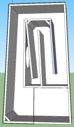
Nice Sketchup drawing. 🙂
For measuring the fold/corners take a look here:
http://www.diyaudio.com/forums/subwoofers/175658-tham15-compact-15-tapped-horn-21.html#post2451737
Work through that page, and if you have the time go through the whole thread. The soho54 method for measuring the corners has been proven to work well; Xoc1's drawing in Post #204 is a nice example.
Your design has a few unneccessary little corner pieces, I would get rid of them, for the wavelengths involved they don't matter; but they may stiffen the box. You might change the bottom lower left hand corner to provide a little less of a jump in the flare around that corner, draw a roll-out like Xoc1 in the reference above.
By the way, you could use TH1 (instead of TH) to give you two sections from the driver to the mouth, that would make the simulation more accurate. You have the same flare that is in the path in front of the driver in the path beyond the driver towards the mouth, and you have a big change @ that lower left hand corner.
Regards,
I'll check out those pages for sure.
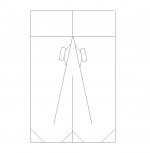
I figured there must be a way to add another section from the driver, that will be very helpful. I've heard those corners don't matter but in my own curiosity, I spent a lot of time trying to visualize how the corners affected volume. I measured each corner and the cross sectional area. You can see the big bumps don't have corners and the small bumps do. I pulled up the corners in 3d mostly for practice, I don't think I would build it that way, although I may put foam in the areas where there is unneeded extra volume.
I realized my power calculations were per voice coil. Was getting to used to working with the Focals. Pretty crazy feeling to feed a single 10 this much power.
Ok back to work.
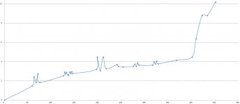
This is a graph I made representing volume and length from S1 all the way through to S4. The left (x) scale is actually 1/4 cross sectional length (so 10 means 40cm). I did that to help with scaling.
Clearly each squiggle is a turn, the large squiggles don't have corners. The corners made it easier to see if he changes in volume are conical, parabolic or exponential. After doing this I determined I should set l12 as Con, L23 as Par and L34 as Exp. Not sure if this is what people do to figure it out.
Clearly each squiggle is a turn, the large squiggles don't have corners. The corners made it easier to see if he changes in volume are conical, parabolic or exponential. After doing this I determined I should set l12 as Con, L23 as Par and L34 as Exp. Not sure if this is what people do to figure it out.
Attachments
What is a 402, other than a Dodge engine block size?
That was out of of nowhere. Pardon me. Abbreviating the amp I mentioned sometime earlier. The Crown 402D.
If you search "402 amp" the first 4 organic terms are for the Crown 402D. I thought everyone would know what I was talking about. I'll say Crown from this point on for those dropping into the conversation late.
Your options seem to be 1.9 ohms or 3.8 ohms, where do you get bridged 8?
Bridged four ohm operation is the same as two amp sides running at 2 ohms.
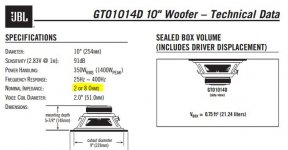
Attachment is from the manual on these speakers. It says 2 or 8 ohm. I guess they consider each of these coils 4ohm? Anyway when I did my calculation I used 1.9ohms and 26v to get 355w, I just forgot there are 2 coils so that's really 710W. Am I right on that at least?
Assuming two parallel side walls, all the horn sections should be modeled as Par.
Ok but why? I want to know! 🙂
Check this out for center line placement:
http://www.diyaudio.com/forums/subwoofers/247110-horn-folding-couple-questions-2.html
I will check that out, thank you.
Attachments
Last edited:
- Status
- Not open for further replies.
- Home
- Loudspeakers
- Subwoofers
- Requesting assistance designing an isobaric tapped horn