Background: My friend has 3 turntables and each is using a Sota Head Amplifier, which amplifies the signal of low output MC carts.
The Sota Head Amplifier is battery powered and come in two versions I know of:
1) One uses disposable D cells and configures the batteries to generate a +1.5v supply and a -1.5v supply.
2) A second design used rechargeable 2.0v lead acid batteries to generate a +2.0v and -2.0v supplies.
The irritation for my friend is he'll forget to turn off the units and the batteries will drain at different rates. So if he wants to A/B two records, he gets two different output levels depending upon the battery status of each head amp, as well as the fact he needs to unscrew the faceplate, remove the casing, and replace the batteries (in the case of the units that use disposable batteries).
He asked me if I could make a common power supply unit that will feed all 3 of his head amps, so at any given time, all 3 units will be seeing the same voltage and will therefore have matched output levels. Also, he won't have to open up each individual head amp, but just the common power supply unit.
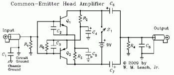
There's no schematic for the Sota head amps that I could find, but attached are a couple of schematics that are probably similar to what the Sota is using.
My thought is to build an external unit that uses rechargeable D cells and feeds each of the 3 head units.
Since the capacity of rechargeables is less than alkalines, I thought I'd use 8 D cells (vs the 6 total currently used for the 3 head amps).
The questions I'm pondering now include:
1) Since the voltage of rechargeables is also less than alkalines (say 1.2-1.25v vs the 1.5v), I'm thinking I should probably series together a pair of rechargeables to generate +/-2.5v supplies versus trying to make the circuit work at +/-1.25v, which might be pushing it since the units are currently operating at either +/-1.5v or +/-2.0v.
2) In addition to the +/- supplies, I think I'll also need to run a ground from power supply unit to ground plane of the head amps.
3) Before I realized I'll probably need a ground, I was thinking of using an RCA cord as my power supply cable. But looking for suggestions on a good 3 connector cable that's relatively compact/streamlined.
Any other feedback is welcome. Thank you.
The Sota Head Amplifier is battery powered and come in two versions I know of:
1) One uses disposable D cells and configures the batteries to generate a +1.5v supply and a -1.5v supply.
2) A second design used rechargeable 2.0v lead acid batteries to generate a +2.0v and -2.0v supplies.
The irritation for my friend is he'll forget to turn off the units and the batteries will drain at different rates. So if he wants to A/B two records, he gets two different output levels depending upon the battery status of each head amp, as well as the fact he needs to unscrew the faceplate, remove the casing, and replace the batteries (in the case of the units that use disposable batteries).
He asked me if I could make a common power supply unit that will feed all 3 of his head amps, so at any given time, all 3 units will be seeing the same voltage and will therefore have matched output levels. Also, he won't have to open up each individual head amp, but just the common power supply unit.
There's no schematic for the Sota head amps that I could find, but attached are a couple of schematics that are probably similar to what the Sota is using.
My thought is to build an external unit that uses rechargeable D cells and feeds each of the 3 head units.
Since the capacity of rechargeables is less than alkalines, I thought I'd use 8 D cells (vs the 6 total currently used for the 3 head amps).
The questions I'm pondering now include:
1) Since the voltage of rechargeables is also less than alkalines (say 1.2-1.25v vs the 1.5v), I'm thinking I should probably series together a pair of rechargeables to generate +/-2.5v supplies versus trying to make the circuit work at +/-1.25v, which might be pushing it since the units are currently operating at either +/-1.5v or +/-2.0v.
2) In addition to the +/- supplies, I think I'll also need to run a ground from power supply unit to ground plane of the head amps.
3) Before I realized I'll probably need a ground, I was thinking of using an RCA cord as my power supply cable. But looking for suggestions on a good 3 connector cable that's relatively compact/streamlined.
Any other feedback is welcome. Thank you.
Attachments

Last edited:
I don't think this will work. It would introduce several ground loops, which I imagine are about the last thing you want when dealing with sub-mV level signals. Plus, with a power supply rejection that might be just about zero, it may not be a good idea to have the battery wiring hanging outside anyway. (At the very least, I would add some RC filtering inside the amp.)
I would suggest making a set of three small independent transformer-based power supplies (could be in one box though), with +/-/GND leads to go to each prepre:
Find the smallest (in capacity) PCB mount transformer that will allow for about 8 V dc (ca. 6.7 V... the nearest standard value is 7.5 V I think) while comfortably delivering enough current... I can't imagine such a circuit would be using more than 10-20 mA per channel (verify!), so even 0.75 VA would seem adequate. You want a conventional split bobbin affair, just very small for minimum mains coupling. (As coupling to both sides of the primary is usually different, it can be optimized by reversing L and N later.)
You could probably make a bridge rectifier out of 1N4148s and even dispense with the usual small parallel capacitors, though it won't hurt to have a few nF there, and/or a snubber. Plan B, find a small DIP case rectifier. Plan C, might as well use Schottkys at these low voltages.
Some decent amount of filter capacitance.
A 78L05 (or 78L06) regulator with a bit of output capacitance as usual, or maybe a capacitance multiplier.
RC filtering and passive rail splitting (maybe 22R - 1000µF||1k, duplicated top + bottom, ground tapped off in between - et voilà, a ca. +/-2...2.25 V split supply).
Another (22R - 470µ) filter each for V+ and V- inside the amp.
It can't hurt to equip the PSU box with an IEC inlet so you also have PE available. As the transformer secondaries ought to have triple-digit pF coupling to mains at most, a mere 4.7 nF Y class capacitor from rectifier (-) to PE should quiet things down in case you can't get rid of hum from transformer leakage current travelling down the signal leads even in the better orientation of L and N. Otherwise the circuits can remain floating just fine.
Last edited:
I don't think this will work. It would introduce several ground loops, which I imagine are about the last thing you want when dealing with sub-mV level signals. Plus, with a power supply rejection that might be just about zero, it may not be a good idea to have the battery wiring hanging outside anyway. (At the very least, I would add some RC filtering inside the amp.)
I would suggest making a set of three small independent transformer-based power supplies (could be in one box though), with +/-/GND leads to go to each prepre:
Find the smallest (in capacity) PCB mount transformer that will allow for about 8 V dc (ca. 6.7 V... the nearest standard value is 7.5 V I think) while comfortably delivering enough current... I can't imagine such a circuit would be using more than 10-20 mA per channel (verify!), so even 0.75 VA would seem adequate. You want a conventional split bobbin affair, just very small for minimum mains coupling. (As coupling to both sides of the primary is usually different, it can be optimized by reversing L and N later.)
You could probably make a bridge rectifier out of 1N4148s and even dispense with the usual small parallel capacitors, though it won't hurt to have a few nF there, and/or a snubber. Plan B, find a small DIP case rectifier. Plan C, might as well use Schottkys at these low voltages.
Some decent amount of filter capacitance.
A 78L05 (or 78L06) regulator with a bit of output capacitance as usual, or maybe a capacitance multiplier.
RC filtering and passive rail splitting (maybe 22R - 1000µF||1k, duplicated top + bottom, ground tapped off in between - et voilà, a ca. +/-2...2.25 V split supply).
Another (22R - 470µ) filter each for V+ and V- inside the amp.
It can't hurt to equip the PSU box with an IEC inlet so you also have PE available. As the transformer secondaries ought to have triple-digit pF coupling to mains at most, a mere 4.7 nF Y class capacitor from rectifier (-) to PE should quiet things down in case you can't get rid of hum from transformer leakage current travelling down the signal leads even in the better orientation of L and N. Otherwise the circuits can remain floating just fine.
Thank you kindly for the reply. I'll have to digest the later part of it, but I do think my friend has a strong preference to remain battery powered vs having a power supply that plugs in the wall.
The whole issue of ground loops was in the back of my mind as a potential issue. I just wasn't sure whether relatively lower voltages such as this generated from isolated batteries would also be subject to ground loops. Assuming the leads going from common battery power supply to each head amp are fairly long (6 ft or so), I would imagine that just makes things worse.
How about the idea of just sending a single power (+/- and no ground) to each head amp and adding a local small PCB within each head amp that takes this voltage and locally splits it into a positive and negative and locally establishes a ground?
I'm just talking off the top of my head and don't have a strong background in electronics, so what I'm thinking may not be possible or may not solve the fundamental problems you detailed.
To avoid ground loops the separate head amps should not be connected except where they reach the main amp. To have a common power supply (of any type) they need to be connected. There is a rule in electronics which says that two or more things cannot be both connected and disconnected.
- Status
- This old topic is closed. If you want to reopen this topic, contact a moderator using the "Report Post" button.