I am looking for a way to determine inductance in the presence of DC current.
With anything having at least two separate windings this is relatively simple: force appropriate current with a high impedance CCS down the secondary winding and measure primary inductance with L-meter - done.
But what about a choke with a single winding ... ?
Is there a method - not too complicated and without expensive equipment ?
I am not after high precision, +/-10% accuracy would be good enough ...
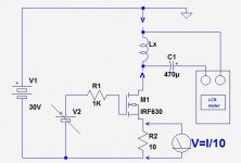
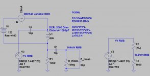
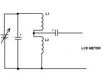
If you already have a GP LCR-meter, the simplest method is to build a small test jig including two variable lab supplies and a few components: pic 1
This is suitable for low frequency applications, and depends on the exact variety of your LCR: some require a DC path in the DUT, and the blocking cap should be omitted, some don't care, and some require a DC path with zero offset, in which case this scheme is not usable.
However, the best method to characterize inductors is to exercise them over their operating domain: that way, you can see graphically their behavior over a range of currents.
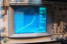
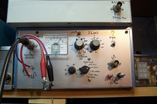
I have built such a jig, and it incorporates additional refinements, like current limit, loss measurement, etc, but basically you need to apply a 10V step (with a function generator+MOS buffer typically) and measure the resulting current over time.
In this example, the slope is 5.6A/50µs up to ~6A, then the inductor begins to saturate, and the slope changes, thus the inductance is 10*500/6=90µH up to 6A, and it is ~halved afterwards.
That is the best method, because it takes into account the large signal inductance rather than the small signal one
This is suitable for low frequency applications, and depends on the exact variety of your LCR: some require a DC path in the DUT, and the blocking cap should be omitted, some don't care, and some require a DC path with zero offset, in which case this scheme is not usable.
However, the best method to characterize inductors is to exercise them over their operating domain: that way, you can see graphically their behavior over a range of currents.
I have built such a jig, and it incorporates additional refinements, like current limit, loss measurement, etc, but basically you need to apply a 10V step (with a function generator+MOS buffer typically) and measure the resulting current over time.
In this example, the slope is 5.6A/50µs up to ~6A, then the inductor begins to saturate, and the slope changes, thus the inductance is 10*500/6=90µH up to 6A, and it is ~halved afterwards.
That is the best method, because it takes into account the large signal inductance rather than the small signal one
Attachments
If you do a search you will find that someone on this very forum posted a circuit which does what you require, and only a few weeks ago.
@elvee:
I tried the cap to hook up my L-meter before, and it doesn't work, the cap seems to fool the meter.
The step voltage looks good, let's see whether I understand it:
- current thru inductor rises linearly when constant voltage is applied to it
I = (V*dt)/L --> L = (V*dt)/I = (10V * 50us) / 5.6A = 89 uH in your example
thank you ...
@euro21:
- basically an AC voltage devider comprised of the impedance of L1 which is Z1=2*pi*f*L1 and R1
many thanks, too.
@df96:
without knowing the poster's name or the exact key word(s) it is very difficult to search the forum and actually find what you are looking for; e.g. a search for "measure inductance" brings up nothing newer than euro21's post from 2011 ...
If I could remember the details I could do the search for you, but I can't so I can't. I can't even remember whether the poster used a valve or a FET to put the DC and AC into the inductor. I do remember that he measured the inductance by adding a resistive load then measuring the LF rolloff. Similarly, he could estimate the stray capacitance by measuring the HF rolloff. Try using synonyms.
Same as what Elvee posted.
- Status
- Not open for further replies.
- Home
- General Interest
- Everything Else
- req: simple method to measure L under DC bias