I recently purchased a Technics SL-6 linear turntable on eBay. A crucial piece of the tonearm assembly was cracked. I ordered a replacement part on eBay and again, that same piece was cracked. So I'm a bit convinced this problem may be due to a design/manufacturing issue. Of course, these things are thirty years old, so there is that.
I wondered if it would be possible to save the motor/platter assembly, and make my own non-linear turntable by adding a more conventional tonearm I'd source on eBay.
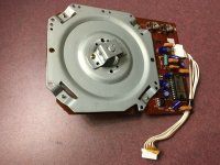
The mechanics of mounting the motor are simple enough for me. But the motor has a board with a 6-pin connector. The connector has one brown and five white wires.
I'm not sure if there is a way to apply power to this board and simply have it spin the platter at 33 or 45-RPM (honestly I don't care about 45-RPM). I'd think if that was possible, I'd see a three-pin connector?
So I figured I'd ask here, maybe someone knows whether what I want to do is possible, or if some of the circuitry needed to control the motor is on the larger "logic" board, to which this board is connected?
My googling has been fruitless.
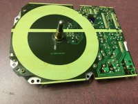
I've posted pics of the model of motor, any thoughts or ideas?
I wondered if it would be possible to save the motor/platter assembly, and make my own non-linear turntable by adding a more conventional tonearm I'd source on eBay.
The mechanics of mounting the motor are simple enough for me. But the motor has a board with a 6-pin connector. The connector has one brown and five white wires.
I'm not sure if there is a way to apply power to this board and simply have it spin the platter at 33 or 45-RPM (honestly I don't care about 45-RPM). I'd think if that was possible, I'd see a three-pin connector?
So I figured I'd ask here, maybe someone knows whether what I want to do is possible, or if some of the circuitry needed to control the motor is on the larger "logic" board, to which this board is connected?
My googling has been fruitless.
I've posted pics of the model of motor, any thoughts or ideas?
Attachments
You need the rest of the electronics and power supply that go with this motor. Alternatively if you have the schematics and sufficient experience you may be able to cobble up what is needed. Based on the questions asked I believe you would be best off to salvage the other bits of off the original table.
You need the rest of the electronics and power supply that go with this motor. Alternatively if you have the schematics and sufficient experience you may be able to cobble up what is needed. Based on the questions asked I believe you would be best off to salvage the other bits of off the original table.
Well that is a shame, but not completely unexpected.
Here is the service manual:
http://www.jpthien.com/temp/technics_sl-6_service_manual.pdf
...as you can see, this table has quite a lot going on. I don't think I could use that other board w/o also using the linear tonearm assembly.
BTW, the reason you indicate I'd need the power supply isn't that I need both 5v and 12v to drive this board, is it? Because if that is the case, I can handle wiring a DC-DC board.
I can't check the existing pin-out reliably because I can't make the thing work because the tonearm isn't working. So the unit will never spin-up the motor.
I can't check the existing pin-out reliably because I can't make the thing work because the tonearm isn't working. So the unit will never spin-up the motor.
Edit to add: Wife left so I had a chance to tie 3, 4, and 5 together and it spins at some high speed. With 4 and 5 tied together, it is spinning very near 33-1/3-RPM. There are two adjustments on the motor itself for 45-RPM and 33-RPM, with instructions to adjust them in the service manual. So I'm fairly confident that any adjustment needed is simply because I switched the power supply, perhaps to a switching supply.
At this point, I'm just curious how I could get the motor controller to spin at 45-RPM...
----------
(My earlier post follows)
Alright I studied the service manual last night and was also able to power-up the old turntable today even though I can't operate the unit because the top cover/tonearm is disconnected.
Pin 1 (brown) seems to be common, pins 2 and 6 are +12vdc. I cut the end off an old wall-wart and wired it like that, and plugged the wart in, no spin but no smoke.
So I added a jumper between 3 and 5 (I think) and the platter spun quite fast. I moved the jumper from 3 to 4 and the unit didn't spin. Finally, I moved the jumper from 4 to 5 and by the looks of things, it was spinning at 33-rpm. I think. The wife came into the workshop area and was showing me something and I stopped.
I'm not sure if anyone is reading this, but would anyone care to take a guess how to get 45-RPM to work? Does tying 3, 4, and 5 together make any sense?
I've linked the service manual in message #3 in case anyone wants to look at it and make any educated guesses.
Last edited:
Final follow-up, in case anyone is following along...
In looking at the schematic they show L being 33-RPM and H being 45-RPM.
I figured I needed to connect pin 3 to 12v. But that didn't work (just super high speed again).
Then I remembered the table has a 33-RPM/auto/45-RPM switch. I had previously tested with the switch set to 33 or auto. So I re-tested with the switch at 45-RPM and saw that pins 4 and 5 now had +12v (whereas there was no voltage there before).
So a quick test with the motor does indeed show that sending +12v over pins 4+5 yields 45-RPM.
So I think I have a working solution for a DIY table motor + platter.
I suppose I should run the motor for an hour or so to make sure it doesn't fry with this wiring arrangement, before I start making a plinth.
This venture required a hands on approach and you've cracked it!
I, for one, would be interested to see the result of repurposing the direct drive motor.
Yes, you're right, I was hoping someone here had already done it, didn't really expect anyone would be able to walk me through the process.
I'm working on tonearm options now. I don't want to spend the bank, so I'm looking at low-cost options on eBay. I'd like a tonearm assembly where the arm cueing lifter and the rest/clip are all built into a single unit. But I don't want to spend SME dollars.
There are some arms from Technics which might fit the bill. Won't be as spiffy looking as a Black Widow or anything, but will allow me to proceed. And if I meet with some success, I can always swap to a different arm later on.
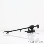
The Pro-Ject Elemental tonearm (1944 191 420) is available as a new replacement part here in the UK for only £60.
About as simple as it gets. Don't know about USA availability though.
They don't seem to have the same sort of deals here.
I may have an old table or two laying around that you can have for the shipping fees
I’ll have to look and see what parts are still there and what tables I have. Let me know if you want one
Well I'd be very interested if there is a tonearm I can harvest. If you let me know the model #'s I should be able to google some images and see if the tonearms would work.

Gemini XL-500II
Sorry it’s missing some parts
View attachment 770497
View attachment 1 View attachment 1
Funny, I was looking at a Gemini tonearm on eBay earlier. I think it checks all the boxes.
I’ll pull the arm out ,that way your not paying for all the weight of shipping, it’s a pretty heavy TT
That would be appreciated!
I'll PM you my address and you can let me know how much for shipping and how you'd like your money (PayPal or whatever).
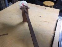
So while I've been looking for an economical tonearm solution (thank you Carl!!!), I decided to try a little experiment.
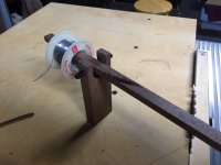
I had also been looking at DIY tonearms and tried to make half a gimbal using some material I scrounged up from the junk drawer and parts cabinet.
The "hinge" is made from two steel ball bearings pushed into the "arm," and two cup-type set screws.
Resistance is higher than I'd like. I'm not sure if a different size ball bearing or set screw would help. If the ball is riding on the edge of the cup, resistance might be higher.
I can see the advantage of the Schroeder tonearm where resistance is concerned, but I have a workable tonearm solution on the way so I'll likely just wait for that now.
But I figured I'd post some pics for fun.
Attachments
Last edited:
You need pin type, hardened set screws for minimal friction. No additional bearing balls, but very small bearings without inner rings instead. And I'm quite sure this wooden arm will resonate like hell.
Best regards!
Because of the shape, or because wood arms resonate a lot?
Because this is just a test to see if I can make a very low resistance joint.
I'm going to get some smaller ball bearings. The current bearings are too large and are riding on the outside of the cup. I need bearings where the D is < the D of the cup, so there is a single point of contact.
- Status
- This old topic is closed. If you want to reopen this topic, contact a moderator using the "Report Post" button.
- Home
- Source & Line
- Analogue Source
- Repurpose Technics SL-6 turntable motor?