I performed a search and didn't find anything specific to the Soundstream amps. I've been busy repairing a CA 6.0 (works now!) and started on two CA 3.0 amps. Since the 3.0's will be driving mids and HLCDs I'd like to upgrade a little bit as I repair them. I'm not after more power, just SQ. With the opamps being TL074 this would seem like a very obvious place to start. There are a lot of pin compatable opamps out there that out perform the TL074. I have some Burr-Brown OPA4134 on hand that I'm going to try. Good move, bad move?
I'm also replacing C206 with an Elna audio grade cap. I going to try to squeeze in an audio grade polypropylene cap for C201. I know the Picasso used poly caps and it was one of the best sounding amps I've heard. Running an audio signal through an electrolytic cap just makes me cringe.
Lastly, looking at the schematic, I can't quite figure out what they are trying to do in the first opamp stage. Forgive me its been 20 years since I messed with opamp circuits. However, it looks like they have a integrator circuit set to low pass at 90KHz. This puts the high frequencies -1.63dB at 20KHz? The thing that bothers me is it looks like the voltage gain of the first stage is 13.4 (+22.5dB). Isn't that pretty high? the second stage is clearly a high pass rumble filter set to 18Hz with a voltage gain of about 1.9 (+5.6dB).
The old Class 50 II, D100 II, and D200 did not have these opamp stages. Why are they in the CA 3.0 and Ref 300 amps? Thanks guys.
Rgs, JLH
Attachments
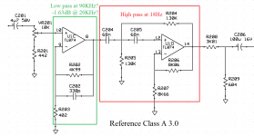
According to the attached graph, it appears that the signal is only down by 0.12dB at 20k.
Interesting. Oh well, I said I was out of practice. That's still a lot of gain that in my opinion doesn't need to be there. Seems you could quiet the noise level of the amp if the gain was reduced.
Rgs, JLH
They may have wanted to get the signal level high enough to swamp out noise from later stages. If the gain was achieved in later stages, that would amplify noise from earlier stages/circuits.
If you find that you have sufficient input signal to easily drive the amp to full power with the gain at the maximum position, you could reduce the gain in this stage to lower the noise floor. I'd prefer to see you do this instead of replacing op-amps.
If you find that you have sufficient input signal to easily drive the amp to full power with the gain at the maximum position, you could reduce the gain in this stage to lower the noise floor. I'd prefer to see you do this instead of replacing op-amps.
To the lower the gain I'm thinking of doing the following: Change R202 to 24.9K, change C202 to 75pF, and change R203 to 49.9K. This should drop the voltage gain of the first stage from 13.4 down to 1.5 while keeping close to the 90KHz low pass.
Rgs, JLH
Rgs, JLH
To the lower the gain I'm thinking of doing the following: Change R202 to 24.9K, change C202 to 75pF, and change R203 to 49.9K. This should drop the voltage gain of the first stage from 13.4 down to 1.5 while keeping close to the 90KHz low pass.
Rgs, JLH
I forgot to mention that I use an Audio Control EQX in my system which can output up to 9.5Vrms, so I have lots of voltage headroom to spare.
I forgot to mention that I use an Audio Control EQX in my system which can output up to 9.5Vrms, so I have lots of voltage headroom to spare.
Most Op-Amp filters use Op-Amp output buffer stages to prevent the filters characteristics from being interfered with by impedance loading related issues that sometimes occur by the next stage. Generally on most car amps you will see a input buffer op-amp stage, then a filter/variable gain stage of some sort, and then a output buffer stage follow up. It may look redundant but you do see it on most every op-amp design that uses any sort of filter or gain control circuit...
If your down on electrolytic's then try Film type caps instead, lots of highly rated SQ amps do this.
Hope this helps some..🙂
A person working for one of the better car amplifier manufacturers recently told me he had very good results on Soundstreams with these simple modifications:
"The SQ upgrades consist of replacing the op amps with higher spec parts (LME49740) and fitting uprated main power supply caps.
On most amps there are 1 or 2 pairs of 1000uF caps, which are way too small. I'm fitting 3300uF 50v radial caps in place of one pair of 1000uF caps and laying them down so they will fit.
The can size is 18 x 35, and there's 19-20mm between the board and back cover so they fit comfortably.
This increases the capacitance from 2000uF to 4300uF per rail, still a bit light for my liking but more than twice as much as standard.
The extra capacity improves power output, and will improve dynamics as the amp will be able to put out more peak current."
But some people believe doing upgrades is quite useless.
I can't comment myself as I have never tried it (yet).
Still slowly working my way through the first 3.0 still. One thing about these amps that never occured to me is the rectification scheme appears to be a pair of half wave voltage doublers. Why? Wouldn't a standard center tapped full wave bridge work as good if not better and be less complicated?
The doubler rectifiers are used to form a bridge rectifier. The transformer drives the center leg. The positive and negative outputs are on the outer legs of the doublers.
Anybody ever see a broken lead on one of the emitter resistors before? R325 is broken right at the pad. I didn't even notice it until I pushed on it so it wasn't touching the diode next to it. I also confirmed that the DC filter caps C122 and C123 are shorted enternally. So, the positive rail popped its caps. I would think about going to some larger caps, but don't want to over tax the rectifiers. Would it be safe to go to a higher value cap? Thanks guys!
Rgs, JLH
Rgs, JLH
I don't have any direct experience with this amp but SS amps are known to have problems with rectifiers. No other amp blows rectifiers as regularly as SS amps.
I've never seen broken emitter resistors in SS amps so I doubt that it's a common fault.
For many of the SS amps, caps of the original value that will fit are difficult to find.
I'd suggest using the same value as the originals.
I've never seen broken emitter resistors in SS amps so I doubt that it's a common fault.
For many of the SS amps, caps of the original value that will fit are difficult to find.
I'd suggest using the same value as the originals.
The rectifiers are indeed strangely problematic.
jandrelectronix@aol.com still has almost all of the original repair parts.
He now also has substitute parts for the rectifiers used on the Reference s / sx series.
I already have purchased some, don't know if they are any better / worse though.
At some point I replaced the rectifiers of a Reference 300 with rectifiers meant for a Reference 500, which are higher rated. Jaime told me it was no problem whatsoever.
Don't know if these higher rated ones would last longer on a less powerful amp ?
The problem with the rectifiers is, that sometimes when they fail, they can damage other components as well.
I checked all the MOSFETs, Darlingtons, and rectifiers. (Did not check all small signal transistors yet) They all test good. I find it odd that the positive rail would pop its caps and there be nothing else wrong. I was thinking I would at least have some bad rectifiers or power supply MOSFETs.
At some point I had a Ref 300 with over 30 volts DC on one of the speakers outputs.
The strange thing is it was an intermittent problem.
In the end we replaced the rectifiers and the problem was solved.
It can't hurt to replace them, at some point they'll need to be replaced anyway.
The strange thing is it was an intermittent problem.
In the end we replaced the rectifiers and the problem was solved.
It can't hurt to replace them, at some point they'll need to be replaced anyway.
SoundStream had to curve trace all their diodes so they made matched spec's, but even with this much effort current sharing was always a issue that lead to failure. Unfortunately dual diodes above 16 amps were not available back then so they had to parallel devices to meet current demand on larger amps. Devices in parallel always fail the weakest device first due to uneven current sharing/mismatched spec's. Both Jaime and Lance made me aware of this long ago. Lance a engineer for SS use to have to curve trace the diodes upon arrival from the factory before SS would use them in any of their amps. 1 ohm current loads are huge on these amps.🙂
Thanks Azvrt and 1moreamp. That is some very useful information. I will take your advice and go ahead and replace the rectifiers while I have it apart. This amp will never see anything below 4 ohms for as long I own it.
I just wanted to thank 1moreamp for the information, but I see you beat me to it.
You can safely go to 2 ohms mono if you wish, that's as far as I go with my beloved amps.
You can safely go to 2 ohms mono if you wish, that's as far as I go with my beloved amps.
Just want to do a reality check before I order parts. Please correct me if I’m wrong on any of the following statements. I can replace the current FED16BTD rectifiers with FEP16DTD. The only difference I see between these two is the BT part is rated at 100V and the DT part is rated at 200V. I can replace the current RFP50N05 power supply FETs with FQP50N06. The difference here appears to be the original part is rated at 50V, while the new part is rated for 60V. In addition, the FQP50N06 also has much lower capacitances. Thanks guys!
GI FED16 Series Datasheets. FED16AT, FED16BT, FED16DT, FED16FT, FED16GT, FED16HT, FED16CT, FED16JT Datasheet.
I only use Soundstream repair parts which I buy from Jaime, so I stuck to the FED16xx parts. At some point I needed to replace the FED16BT rectifiers from my Ref 300 (same as 3.0) but I only had FED16CT in stock which Jaime had sold me to repair a Ref 500. He told me I could use these and I did. They are rated at 150V instead of 100V.
The FEP16DT part you mention is used in pairs with FEN16DT for the Reference s and sx amplifiers. I am not sure, but I'd not use these on your original Ref.
Contact Jaime over in Sacramento for the right parts, that's the best advice I can give you, though Perry might have something more useful to say on the matter than I.
- Status
- Not open for further replies.
- Home
- General Interest
- Car Audio
- Replacing TL074 opamp in Soundstream CA 3.0