
I repaired a PD-8500 4 years ago and at the beginning I thought that buying the IR was the only option to go through the different steps of the TEST mode.@Uladz Sadly the RC is necessary for this specific model. Just for tracking loop control, but neccesary.
Then I realized that << and >> buttons (available only on the remote) were only need to move the carriage to a given position, which can be carefully done by hand.
What is important is that you can access >>|, PLAY and PAUSE which respectively triggers FOCUS SERVO, SPINDLE servo and PLAY mode...but these buttons are available on the device.
So long story short, at least for me, RC is not (strictly) needed.
Hello friends!
I think that the remote control will be useful in the future.
There are track search buttons on the front panel, but there is no fast forwarding.
And the volume at the player’s output is adjusted using the remote control in a similar way.
It’s also convenient, you don’t need to turn down the volume on the amplifier.
The remote control will arrive, there will be a second series on CD repair.
All the best to you. Vladislav
Hi guys!
Today I finished tinkering with the Pioneer PD -8500.
The remote control arrived and things started to work.
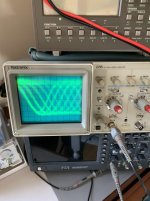
In test mode (electronics turned off), I configured the grid.
A homemade 75mm test disc came in handy.
I did not remove the tray and all the screws for adjusting the planes are accessible from behind the disk (75mm).
There is a rhombus made of sinusoids in the photo; all edges of the rhombus should be as tight as possible.
After exiting the test mode, the automatic electronics adjusted the laser.
Reads discs quickly.
Out of 50 discs, only one jumped.
It was recorded on a computer.
Original discs can be read and rewound with confidence.
Even scratched discs can be read without problems.
Thank you friends that you and your site pushed me to restore this well-made car.
I got a great experience from this work.
DACs PCM 63, this is a great sound from this CD.
Best regards, Vladislav.
Today I finished tinkering with the Pioneer PD -8500.
The remote control arrived and things started to work.
In test mode (electronics turned off), I configured the grid.
A homemade 75mm test disc came in handy.
I did not remove the tray and all the screws for adjusting the planes are accessible from behind the disk (75mm).
There is a rhombus made of sinusoids in the photo; all edges of the rhombus should be as tight as possible.
After exiting the test mode, the automatic electronics adjusted the laser.
Reads discs quickly.
Out of 50 discs, only one jumped.
It was recorded on a computer.
Original discs can be read and rewound with confidence.
Even scratched discs can be read without problems.
Thank you friends that you and your site pushed me to restore this well-made car.
I got a great experience from this work.
DACs PCM 63, this is a great sound from this CD.
Best regards, Vladislav.
Attachments
Thank you Mauricio!
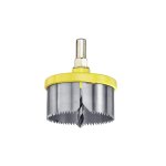
For such a disk you need a wood cutter with a diameter of 75-80mm.
Such cutters are used by carpenters when they make holes for sockets for electric plugs, with small teeth.
The photo shows a sample.
Could not send video, more than a minute 70 MB.
Great site!
You can now help people and solve similar problems. A laser like this appeared on Alliexpress (500 euros), but installing it requires exactly the same procedure as replacing a laser diode.
With respect to you and to all forum participants, Vladislav.
Great weekend to everyone!
Attachments
Sorry if I post in the wrong forum, but you people seems to know a lot about the PD-8500.
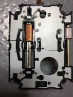
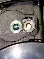
Found one in nice condition, but there is a stop on the laser sledge witch I do not understand.
It is the small thing sticking out in the sledgetrack, please follow the red arrow.
Thankfully everything else seems to be working, I really do not believe that a thing as complicated and delicate as this player once was in series production.
/ SWIN
Hi Swin, I don´t know a lot of this CDP. Just curiosity.
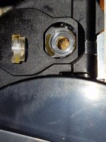
Regarding to you question, there should not be any stopper on the run way.
Check that the carriage runs freely from the inner to the outside of the disc. The guide must reach both ends of the cilindric shinny rod bar at left of your picture. If you look near, may be observe thiny rubber bumpers on the extremes.
Then remove it mercilessly.
Let know us about your results.
Hello everyone!
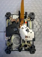
This is a great sliding mechanism.
There should be nothing foreign on the moving parts.
Such chips happen when the plastic cracks along the edges from old age. It can create problems for the pickup to slide.
This is treated by removing the entire vehicle and putting the cracked plastic back in place from the back, pressing it down and carefully heating the break with a soldering iron and connecting.
The glue will not hold the cracked areas.
The burrs in the plastic will interfere with the laser.
I marked it with arrows. ▶️
Best regards, Vladislav.
Attachments
Thank you, will try to remove it.Hi Swin, I don´t know a lot of this CDP. Just curiosity.
Regarding to you question, there should not be any stopper on the run way.
Check that the carriage runs freely from the inner to the outside of the disc. The guide must reach both ends of the cilindric shinny rod bar at left of your picture. If you look near, may be observe thiny rubber bumpers on the extremes.
Then remove it mercilessly.
Let know us about your results.
Also thank you, good picture - I thought it was some kind of extra lockingmechanism, will try to correct it.Hello everyone!
This is a great sliding mechanism.
There should be nothing foreign on the moving parts.
Such chips happen when the plastic cracks along the edges from old age. It can create problems for the pickup to slide.
This is treated by removing the entire vehicle and putting the cracked plastic back in place from the back, pressing it down and carefully heating the break with a soldering iron and connecting.
The glue will not hold the cracked areas.
The burrs in the plastic will interfere with the laser.
I marked it with arrows. ▶️
Best regards, Vladislav.
All this complicated clock watch precision machinery, just to read a CD.
Really - they do not build them like this any more.
Hej Swin!
Detta är en CD-spelare med mycket bra ljud baserad på PCM 63 DAC.
Rengör sedan den ena sliden, där det finns två gummiband, och smörj in lite med teknisk vaselin störa driften av lasern
Lycka till med att återställa din enhet.
Det kommer att finnas frågor, skriv.
MVH/Vlad
Detta är en CD-spelare med mycket bra ljud baserad på PCM 63 DAC.
Rengör sedan den ena sliden, där det finns två gummiband, och smörj in lite med teknisk vaselin störa driften av lasern
Lycka till med att återställa din enhet.
Det kommer att finnas frågor, skriv.
MVH/Vlad
hi,I got a PD6050,it can't read,and it seams use PWY1010,i remove the laser diode hardly,because i don't have manual. i have 2 question,1The objective lens has fallen off, how to determine if it is usable, and how to remove the original glue and use what new glue to fix it? If I have completed the assembly, how should I debug it? I have some music CDs and a dual channel oscilloscope. By the way, can someone provide a manual for 6050? I have a general manual for 70, 60, 50, and 40, but there isn't much useful information.
Hello! Do not remove the old glue from the lens and the seat yet. Put the lens in the socket and look at the glue spots to see how the lens was installed. Mark the lens seating spots with a marker, take a few photos and after that you can carefully remove the glue. Best regards, Vladislav.
To install the lens, you don't need to disassemble the vehicle, or more precisely, the pickup with the laser. It's enough to remove the plastic cover, very carefully.
Thank you,My module is quite different from yours. I have replaced it with a new LD and installed the lens. Power on, but there is no light and the camera won't move up and down. I reread the post and it seems like I missed a grounding wire under a screw. Is this a problem? I don't think so. I've already spent too much time today, and I'm planning to try installing the grounding wire tomorrow. I also tested the RF pins with an oscilloscope, and there were no waveforms, only messy waveformsHello! Do not remove the old glue from the lens and the seat yet. Put the lens in the socket and look at the glue spots to see how the lens was installed. Mark the lens seating spots with a marker, take a few photos and after that you can carefully remove the glue. Best regards, Vladislav.
Hello! I bought a Pioneer PD-2000 from Japan. When I arrived, I heard something moving inside. When I took the cover off, I discovered that the laser lens had come off from the glue. see the attached pictures. Since you are well acquainted with changing lasers, my question is - is it possible to put this lens back, and if so, how? Thanking you in advance, Meelis
Attachments
When the glue matches, make two marks on the side of the lens and on the seat. Only then carefully remove the old glue on the lens and seat. Before cleaning the glue on the seat, cover the hole with cotton wool. This way, glue residue can get on the lens mirror. After the entire procedure, blow out the lens pickup and apply three small drops of wood glue to the seat, you can use the tip of a needle or toothpick, as if the triangle is not visible. Then put the lens as it was marked, also removing the glue from it and wiping it. You can press the lens with an ear stick and hold it for a minute so that the glue sets. After 30 minutes, you can try testing. If you are afraid to do everything, you can bring it to Riga, I will do it if the laser is alive.
Best regards Vladislav
Best regards Vladislav
- Home
- Source & Line
- Digital Source
- Replacing Laser Diode in PWY1011 (Pioneer PD-717, PD-737, PD-7100, PD-7300, PD-8500, PD-9500, PD-71, PD-73, PD-2000LTD)