Hello everyone,
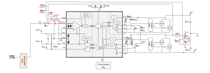
I am following a reference design from Infineon based on their new IRS2461S IC (attached below). The IC contains an OTA + MOSFET Gate Driver, and I have chosen to replace it with an Op-amp + external MOSFET Gate Driver IC.
My question is whether I should do further changes to the modulation scheme to make it work, or if the modulation scheme will operate as is with the op-amp.
I have also noticed that the capacitor labeled DNP in the attachment is always taken out when switching from (IRS2092) to (IRS20957 + op-amp). Am I correct in choosing to not populate that capacitor for my final schematic design?
Thank you,
Attachments
Interesting question, when I usually look at varies class d app notes (especially the old IR ones) I see that the feedback is two resistors in series with a capacitor to the ground between them.. never saw this type of connection before..
and regarding the capacitor, I think it has to do something with OTAs? perhaps I'm wrong?
I hope you get an answer from other members who are experts in the theory of class d amplifiers! Because the IRS2092 is almost out of stock everywhere by now! So people are moving their designs to normal mosfet gate driver ICs... like the SI8244
If I'm not wrong, that's just the integrator in the sigma-delta style self-oscillating modulator.I see that the feedback is two resistors in series with a capacitor to the ground between them.. never saw this type of connection before..
Actually, there's an even simpler way to avoid the IR chips, Just take the feedback from after the filter (at the output capacitor) like at the following link. Once the feedback it done, the comparator output maybe wired to a gate driver like the Si8244 to run the output stage.Because the IRS2092 is almost out of stock everywhere by now! So people are moving their designs to normal mosfet gate driver ICs... like the SI8244
Philips UM10155
There's also a 10+year old thread on this topic here:
https://www.diyaudio.com/community/threads/ucd-25-watts-to-1200-watts-using-2-mosfets.166214/
Last edited:
Well - you can but you won't get the obvious features: OC, OT ect.Hello everyone,
I am following a reference design from Infineon based on their new IRS2461S IC (attached below). The IC contains an OTA + MOSFET Gate Driver, and I have chosen to replace it with an Op-amp + external MOSFET Gate Driver IC.
My question is whether I should do further changes to the modulation scheme to make it work, or if the modulation scheme will operate as is with the op-amp.
I have also noticed that the capacitor labeled DNP in the attachment is always taken out when switching from (IRS2092) to (IRS20957 + op-amp). Am I correct in choosing to not populate that capacitor for my final schematic design?
Thank you,
Also, you will need to do a lot more work around making sure the system oscillates, there are smaller blocks in the IC not shown to make the thing work with known propagation delays to setup the system.
If you want a an external op-amp + driver you will need to start from the point of a system, not this IC schematic.