You could measure the resistance (of a healthy bulb) and put an R in its place. It would be necessary to see where that "fuse" is, probably it is not part of the xover. (it shouldn't)Removing the bulb and polyswitch protection may alter to overall balance of the crossover. You may be able to do it, just may require some additional crossover tweaking in that case.
It's an FRS-11Can you give us the exact model of your Ohm speaker? I would like to explore the web about it. Maybe I'll find the xover diagram and that might help get all the protection part out.
And yes, you are right, a well used speaker cabinet would not need protection, usually when they go bad (mainly the tweeter, the weakest part) it is because the amplifier failed and delivered DC.
And there were few "vintage", but to purists that was heresy because they "interfere with the signal path")I'd venture to say most home speakers don't have fuses anymore.
Technbics SB1950 for example, I have one of them. I never needed to activate it, it's a small circuit with an IC that triggers a mini knob inside a "special" relay, if you press it again, it stays activated again. They are not very fast, the one that attaches to you before is much superior.
The poly switches appear identical but measure way differently. So at least one is "bad". I looked up specs on similar devices and it seems like they shouldn't have any resistance when "open".As far as I understand polyswitch, it should have some low resistance and will have higher resistance in a fault condition. Any chance you can draw a schematic from what is there? There is a good chance the polyswitches are good.
You may just need to get a replacement bulb.
Removing the bulb and polyswitch protection may alter to overall balance of the crossover. You may be able to do it, just may require some additional crossover tweaking in that case.
Also there is a good chance you can secure a close enough replacement bulb at your local auto parts store. Mostly look for 12V 2A.
A response I got from someone at ohm said "If tripped repeatedly, this device can become overly sensitized and it can clamp down at a much lower level than it should. The speaker wouldn't stop playing altogether, it would just sound strangely quiet". Not sure if the device he was referring to was the bulb or the switch.
Yes. Some speakers have had protection circuits over the years. It's pretty rare these days. I think I can do without it 🙂There were a few, but to purists that was heresy because they "interfere with the signal path")
Technbics SB1950 for example, I have one of them. I never needed to activate it, it's a small circuit with an IC that triggers a mini knob inside a "special" relay, if you press it again, it stays activated again. They are not very fast, the one that attaches to you before is much superior.
Could you trace all of the parts and draw a schematic? Looking to see how the polyfuses are attached along with the bulbs.
Some of us might spend too much time wondering what they did and it will cause us emotional pain.
Some of us might spend too much time wondering what they did and it will cause us emotional pain.
You could measure the resistance (of a healthy bulb) and put an R in its place. It would be necessary to see where that "fuse" is, probably it is not part of the xover. (it shouldn't)
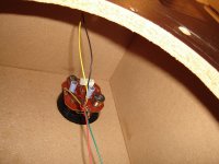
There should be a picture posted at the beginning of this thread that shows the bulbs in white fabric insulation. They are wired in between the large capacitor and the woofer and a resistor and the tweeter.
Could you trace all of the parts and draw a schematic? Looking to see how the polyfuses are attached along with the bulbs.
Some of us might spend too much time wondering what they did and it will cause us emotional pain.
I could try. Lol. There's a picture at the beginning of this thread showing the crossover and here's something I wrote to try and explain all the connections while looking at that photo...
So...the red wire coming from the red speaker binding post connects to the upper lead on the 750 uf cap. Pictured below that cap is a pair of glass "light bulb" fuses in those two white fabric sleeves, and the one on the left has a polyswitch (looks like a small ceramic capacitor) in parallel with it. The lower lead on the 750 uf cap connects to BOTH the left lead on the "bulb" on the left AND to the polyswitch. Here's where it gets complicated. The right lead on that left bulb (which you can't see) connects to both the other end of the polyswitch, and the left lead of the "bulb" on the right. That three way connection travels down and is connected to the woofer's positive connector. The right lead on that "bulb" on the right connects to the lower lead of the yellow 4.7k resistor. The upper lead of that resistor goes to the positive connector on the tweeter. The white wire is connects to the negative lead of the tweeter (hidden behind the 750 uf capacitor) and connects to the negative lead of the woofer and negative speaker wire.
As far as the two inductors, the smaller one on the left is wired in parallel with the tweeter. It's connected to tweeter positive (out of view) and the negative connector on the woofer. The larger inductor on the right is connected in parallel with the positive and negative woofer connectors.
Here it is, it doesn't even have an IC....And there were few "vintage", but to purists that was heresy because they "interfere with the signal path")
Technbics SB1950 for example, I have one of them. I never needed to activate it, it's a small circuit with an IC that triggers a mini knob inside a "special" relay, if you press it again, it stays activated again. They are not very fast, the one that attaches to you before is much superior.
I'm sorry, but don't you think that if you ask for help, you should do the job yourself ? 🙄
Following your description is not very clear, moreover.
Attachments
That inductor in parallel with the woofer has me a bit perplexed? I have built alot of crossovers and never done that unless the woofer had a limited low frequency range. Hoping it has alot of inductance and some DC resistance. Maybe paired with the 750 microfarad cap it is meant as a high pass filter to keep you from damaging the woofer. Should give a rolloff in the 30 hz range
Where do the tweeter leads connect?
Where do the tweeter leads connect?
This is my first time doing this, lol...As far as I understand polyswitch, it should have some low resistance and will have higher resistance in a fault condition. Any chance you can draw a schematic from what is there? There is a good chance the polyswitches are good.
You may just need to get a replacement bulb.
Removing the bulb and polyswitch protection may alter to overall balance of the crossover. You may be able to do it, just may require some additional crossover tweaking in that case.
Also there is a good chance you can secure a close enough replacement bulb at your local auto parts store. Mostly look for 12V 2A.
Not sure if the device he was referring to was the bulb or the switch.
It will have been the polyswitch.
If a polyswitch is subjected to prolonged overload, it will not return to its normal low value, but ends up high resistance.
There two circumstances where tungsten bulb series tweeter protects it. 1 Microphone is dropped on-stage. 2. RCA or phono plug is pulled out, making a loud pop!
You can ignore one if you don't use microphones on stage. I have, however, walked over preamp to amp cabling and pulled it out. I blew a 3" cone tweeter somehow, with a 35 w/ch tube amp. KLH23 2 way speaker, dynakit ST70 amp. I wish I'd had the tungsten bulb. That speaker sat in my garage/attic 30 years until diyaudio came online and I learned a lot of things.
My current Peavey SP2(2004) speakers have the tungsten bulb, and sound better than the repaired (or the undamage) KLH23 without bulb at the 1/8 to 50 watts I listen to it in my music room. I view fear of the tungsten bulb unwarrented. Polyswitches do wander value off if tripped repeatedly. Peavey doesn't use them I don't believe. You can calculate the proper cold value of a bulb if you know the wattage of the speaker and the desired impedance. Usually a 1 ohm cold bulb pulls the speaker (6.5 ohm resistive is my SP2 woofer) up to 8 ohms.
Tungsten bulbs sold for 300 w AES PA speakers will be too forgiving for a home speaker.
Last edited:

Have you looked at both crossovers yet? I just want to be sure that inductor in parallel with the woofer is really right. Also have you listened to the one with a good bulb and can say it sounds right?
It would need to be in the 10-20 mH range to be right. If it is a small value, it may be that the previous owner attempted to fix something and did a bad thing. Does that inductor across the woofer appear to have a ferrite or iron core?
Also the yellow 4.7 capacitor should be in series with the tweeter and have the choke from tweeter to ground as drawn.
I have also seen a preamp oscillate due to poor design and take out a tweeter. Bulb would have saved the tweeter from that.There two circumstances where tungsten bulb series tweeter protects it. 1 Microphone is dropped on-stage. 2. RCA or phono plug is pulled out, making a loud pop!
You can ignore one if you don't use microphones on stage. I have, however, walked over preamp to amp cabling and pulled it out. I blew a 3" cone tweeter somehow, with a 35 w/ch tube amp. KLH23 2 way speaker, dynakit ST70 amp. I wish I'd had the tungsten bulb. That speaker sat in my garage 30 years until diyaudio came online and I learned a lot of things.
My current Peavey SP2(2004) speakers have the tungsten bulb, and sound better than the repaired (or the undamage) KLH23 without blub at the 1/8 to 50 watts I listen to it in my music room. I view fear of the tungsten bulb unwarrented.
Yes. They're identical.Have you looked at both crossovers yet? I just want to be sure that inductor in parallel with the woofer is really right. Also have you listened to the one with a good bulb and can say it sounds right?
It would need to be in the 10-20 mH range to be right. If it is a small value, it may be that the previous owner attempted to fix something and did a bad thing. Does that inductor across the woofer appear to have a ferrite or iron core?
Also the yellow 4.7 capacitor should be in series with the tweeter and have the choke from tweeter to ground as drawn.
I removed the poly switch from both as well. That's how I measured them.
Both speakers sound the same. That is to say...very low, weak sound.
I don't think anyone has touched these internally since they were made in the 80's. There is a wire can/cage you have to remove to get to the parts. It had never been removed. There are other pictures online that show this same crossover setup.
Last edited:
I made my first ever crossover diagram in post #31 if you were unable to follow my description while following along with pic I posted in post #1.Here it is, it doesn't even have an IC....
I'm sorry, but don't you think that if you ask for help, you should do the job yourself ? 🙄
Following your description is not very clear, moreover.
The conventional connection for a two-way xover is a capacitor in series with the tweeter to block low frequencies. In its place is a coil, which is typically used to block mid/high frequencies from going to the twoofer. (Which isn't always necessary, since if it's a large twoofer, those frequencies won't even tickle.)
So I think that this connection is the work of some manipulation by someone not very expert and that explains the horrendous manufacturing that is seen in the OP's photo.
Ohm made speakers with unconventional physical configurations, such as speakers pointing toward the zenith. We do not know
Try to get the original circuit, or go to them. I'm out.
https://ohmspeaker.com/legacy-products/frs-11/
Ohm doesn't share data. They stay in business by having you pay them fix it. The crossover is original. Other pics online show the same setup. Adios.
You should be able to get away with shorting the first lamp and polyfuse. See how they sound. The lamp for the tweeter is more critical than the woofer.
Also could you get some pictures of the inductor in parallel with the woofer? I just want to make sure it appears to be an appropriate value. It would only be an appropriate use if it has a fairly high inductance. Just attempting to guess the value by sight.
Also could you get some pictures of the inductor in parallel with the woofer? I just want to make sure it appears to be an appropriate value. It would only be an appropriate use if it has a fairly high inductance. Just attempting to guess the value by sight.
- Home
- Loudspeakers
- Multi-Way
- Replacing fuse bulbs in vintage speakers? Modern alternatives?