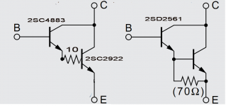
I have laying some nice schematics where power section is triple darlington style output stage (which is formed using 2SC3221>2SC4883>2SC2922 , but I have a bunch of 2SD2561 Sankens with I like to use for the last two stages. picture explains it all.
apart ability to acess inner base to add 10ohm (together with no ability to disconect that internal 70ohm resistor) what are drawbacks of this circuits? any bias issues and sonic penalties?
thanks a million
apart ability to acess inner base to add 10ohm (together with no ability to disconect that internal 70ohm resistor) what are drawbacks of this circuits? any bias issues and sonic penalties?
thanks a million
Attachments
The inability to disconnect the 70 ohm resistor results in forcing all the driver stage quiescent current through the emitter resistor. There is no good accurate way to set the output stage bias, and you are at the mercy of how well the NPN and PNP match for vbe (and Rbe resistor value). The lack of a base stopper isn’t the end of the world. I typically only add them when paralleling outputs.
wg_ski,The inability to disconnect the 70 ohm resistor results in forcing all the driver stage quiescent current through the emitter resistor. There is no good accurate way to set the output stage bias, and you are at the mercy of how well the NPN and PNP match for vbe (and Rbe resistor value).
I agree that a packaged darlington is not the best choice for an output stage, primarily because it is difficult to turn off the output transistor quickly. But, I am not sure that I understand some of your statements. The bias in the driver is fixed at about 10 ma by the 70 ohm resistor. This may not be optimum and as you point out, it ends up in the output transistor's emitter resistor. It would seem that 10 ma is probably not large compared to the output stage bias and is fairly constant. So, why does this make it difficult to set the output stage bias? Also why does NPN and PNP match become more of a problem? I must be missing something.
Bruce
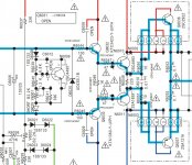
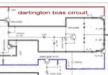
elviukai,OK, thanks. So without modyfing biasing schematic you would not recomend use darlingtons? ataching both amps bias schematic
The "bipolar bias.jpeg" schematic you attached is clearly a triple darlington connection. I am not quite sure what I am I am looking at in the second schematic. It looks like a two transistor compound connection and I do not see a 2SD2561 called out on it. I assume the final transistors are darlingtons, but the pre-driver now makes a compound connection instead of darlington. Is that correct? Could you clarify, please? Thanks.
Bruce

Hi Bruce, thanks for chime in. bias schematics named "darlington: have 2sa1360 as VAS which goes directly to 2SD2561( for some reason its just simply not marked as darlington but rather shows as single trasistor, but its 2SD2561) the other shematics have aka "discrete darlington topology"(2SC3221>2SC4883>2SC2922 )
so i would like to use 2SD2561 instead 2sc4883/2sc2922 ( it could be that in 2SD2561 other smaller die is very similar to 2sc4883. and all 3 trasistors is sanken anyway.. ) my wory is that i have permanent 70ohm resistor in 2SD2561 and how it will affect when put in that circuit of 2sc4883/2sc2922 combo. I have minimal amplifier knowledge, so better ask than burn 🙂
so i would like to use 2SD2561 instead 2sc4883/2sc2922 ( it could be that in 2SD2561 other smaller die is very similar to 2sc4883. and all 3 trasistors is sanken anyway.. ) my wory is that i have permanent 70ohm resistor in 2SD2561 and how it will affect when put in that circuit of 2sc4883/2sc2922 combo. I have minimal amplifier knowledge, so better ask than burn 🙂
In practice, the NPN and PNP outputs won’t start turning on at the same time as you turn up the bias. The Vbe is not constant (or even necessarily the same between NPN and PNP) - it goes up a tenth or so for every decade of current. It may be down at half a volt when you start seeing output stage current. There will be two places where the total current (which is what you measure) starts to rise more rapidly. It’s just not a smooth curve like the conventional circuit has. With driver current excluded, the output pair is forced to the same current, and the output current is all you measure. The bias can be exactly set to 26mV/Re, if you are so inclined. And if you want to save dissipation as much as possible, it’s easy to get 2 or 3 mV across the resistors - and know that the bias in both outputs is the same. With the darlingtons , either you put up with matching problems at low current or you just overbias the hell out of it to swamp out the differences.wg_ski,
I agree that a packaged darlington is not the best choice for an output stage, primarily because it is difficult to turn off the output transistor quickly. But, I am not sure that I understand some of your statements. The bias in the driver is fixed at about 10 ma by the 70 ohm resistor. This may not be optimum and as you point out, it ends up in the output transistor's emitter resistor. It would seem that 10 ma is probably not large compared to the output stage bias and is fairly constant. So, why does this make it difficult to set the output stage bias? Also why does NPN and PNP match become more of a problem? I must be missing something.
Bruce
Note that R6049 resistor in your 1st schematics, paralleled with C6010, between both driver transistor emitters. This combo significantly speeds up the power devices, which isn't possible with the driver transistor's emitter resistor returned to the common emitter pin in a Darlington.
Best regards!
Best regards!
Yes! This was my primary concern that I alluded to in post #4 before I looked at the schematic.Note that R6049 resistor in your 1st schematics, paralleled with C6010, between both driver transistor emitters. This combo significantly speeds up the power devices, which isn't possible with the driver transistor's emitter resistor returned to the common emitter pin in a Darlington.
Best regards!
Last edited:
You are correct. In this particular case, Re = 0.1 Ω (very low), so if you set to the Oliver point, the output stage bias should swamp out the driver bias pretty well. I don't think that setting the bias to this point would be particularly difficult. More important, perhaps, is the transition through the crossover region with signals. I have not thought this through yet, but you make me wonder if the transition is also less smooth with the packaged darlington. What do you think?With the darlingtons , either you put up with matching problems at low current or you just overbias the hell out of it to swamp out the differences.
Thanks guys! So to conclude- 1) i can replace with true darlingtons, and just watch bias and thermal runaway upn heavy load. fortunately its AB class amps. 2) replacement will lead to worse performance, which can be heard /or measured.
elviukai, sorry for the slow response, Time zone differences don't help. I don't want to speak for wg_ski or Kay Pirinha, but I am pretty sure that the three of us would agree that what you want to do could probably be done given enough care, but it is not a good idea. Distortion at high frequencies may suffer from the inability to quickly turn off the output transistors, and the bias may be difficult to set and may not be stable. Regarding the latter, in addition to what has been discussed above, the driver transistor would be in a whole different thermal environment within the darlington package than as a separate device. Thus, the bias compensation scheme may have to be altered to track properly. BruceI have minimal amplifier knowledge, so better ask than burn 🙂
Bruce, its not slow by any means.It so nice to get professional opinions. Original darlingtn schematics (VFB, using toshibas 2240/970 as LTP, 1360/3223 VAS and then directly to sanken darlingtons, ) sounds quite nice. the ones I want replicate with darlingtons instead of dicrete last two stages are CFB, and are much more sophisticated and better spounding ( surpsisingly in cosists of more than double stages ,so simpler is not always better ) .If I can achieve better sound lets say 85% of discrete circuit i will be happy. having 26psc sanken MT200 darlingtons in my drawer pushes this experiment. Genue Sankens are costly those days (the cheapest ones is 16eur/pair and i need 24 pairs )
The driver transistors in canonic EF output stage must work in unswitchable mode.
Every darlington includs driver transistor, but its iddle current so low what driver transistor generate switching distortions.
It can be heard.
Every darlington includs driver transistor, but its iddle current so low what driver transistor generate switching distortions.
It can be heard.
I definately agree that crossover discortions could be heard. suprisringly its not always for worse. 😀 I had a 5 stage apmlifier (front end opa on opa627) which refused to be biased deeper in class a- as soon as I adjusted output transitors(20psc) for 40mA( 0.8A)or so amp bias started to increase over 20-30min to 70mA and still rising. so it would blow up at some point. I tried put drivers and predrivers on same heatsink-nothign helped. than I played with 3 gains stage bias and bingo. in short- i needed to increase in two of gain stages bias as it was VERY LOW ( few mA!) once increased it prevented form thermal runaway . i install switched for class A few levels and let amp play. i did not heard any beneft when swithcing between bias but amp sounded noticeable worse than it was before upgrade. i intalled another 8mini dip swithec to play with other stage bias. so quess what- most natural , not etched hights sound was with low bias on all stages. I repeated my findings with friend of mine on blind test and he confrmed same findngs. so seems not always larger bias is better. .
- Home
- Amplifiers
- Solid State
- Replacing Driver/output transitor combo with single darlington?