I have an amplifier project I have been working on for several months now and have already built two versions of. I've attached the most recent schematic to this message. The amplifier is working fine and uses MJL3821A/MJL1302A BJTs as the power output transistors.
My friend and I who have been working on this project want to try something different, and use the ECW20N20 and ECW20P20 lateral MOSFETs to see if the bandwidth/slew rate/distortion might be improved using the MOSFETs.
I have a few questions about what changes:
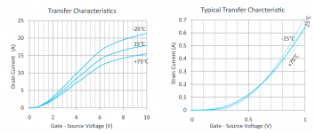
1. In the schematic below, there is a bias servo that limits the quiescent current as the transistors heat and their emitter-base voltage decreases. In a class AB configuration with MOSFETs, the voltage between the gates of the N and P channel MOSFETs determines the quiescent current, which is in turn dependent on the threshold voltages of the MOSFETs. The ECW20N20 drain current increases with temperature below a certain Vgs (0.6 V, see attached graph) and decreases with temperature above this voltage, for example. Therefore the drain current will self-limit if the threshold voltage is above 0.6 V. Do I need to worry about the region below 0.6 V, or could I just set the bias to a fixed voltage and allow the transistor drain current to self-regulate with temperature?

2. When paralleling BJTs, one can use base stopper resistors to suppress oscillations, or sometimes omit them. When paralleling MOSFETs, one must use gate resistors or otherwise the two joined gates could oscillate with the capacitance of the gates resonating with the series inductance of the connection between them. How does one choose the value of these gate resistors? If they are too small, they do not suppress oscillation, and if they are too large the gates charge too slowly. Is it approximately sqrt(L/C) with L being the inductance of the trace and C between the series capacitance of the two gates? Because one of the major benefits of using a MOSFET vs BJT is only needing to charge the gate rather than continuously draw current, keeping this resistance to a minimum is key to making the transistor slew fast in voltage.
3. Similarly, how big should source resistors be on the lateral MOSFETs? They should in theory share current because the drain current should drop as the transistor heats, however, this depends on good thermal sinking between the devices and the devices being above the 0.6 volt threshold.
4. Are there any breakdown or failure mechanisms that occur with lateral MOSFETs that are not commonly known? They are supposed to be very rugged as far as I have heard, supposedly being superior to BJTs in that they do not have secondary breakdown and a negative transconductance with temperature. Are they really worth it compared to the BJTs I have already used MJL3281A/MJL1302A?
Thanks for any answers.
My friend and I who have been working on this project want to try something different, and use the ECW20N20 and ECW20P20 lateral MOSFETs to see if the bandwidth/slew rate/distortion might be improved using the MOSFETs.
I have a few questions about what changes:
1. In the schematic below, there is a bias servo that limits the quiescent current as the transistors heat and their emitter-base voltage decreases. In a class AB configuration with MOSFETs, the voltage between the gates of the N and P channel MOSFETs determines the quiescent current, which is in turn dependent on the threshold voltages of the MOSFETs. The ECW20N20 drain current increases with temperature below a certain Vgs (0.6 V, see attached graph) and decreases with temperature above this voltage, for example. Therefore the drain current will self-limit if the threshold voltage is above 0.6 V. Do I need to worry about the region below 0.6 V, or could I just set the bias to a fixed voltage and allow the transistor drain current to self-regulate with temperature?

2. When paralleling BJTs, one can use base stopper resistors to suppress oscillations, or sometimes omit them. When paralleling MOSFETs, one must use gate resistors or otherwise the two joined gates could oscillate with the capacitance of the gates resonating with the series inductance of the connection between them. How does one choose the value of these gate resistors? If they are too small, they do not suppress oscillation, and if they are too large the gates charge too slowly. Is it approximately sqrt(L/C) with L being the inductance of the trace and C between the series capacitance of the two gates? Because one of the major benefits of using a MOSFET vs BJT is only needing to charge the gate rather than continuously draw current, keeping this resistance to a minimum is key to making the transistor slew fast in voltage.
3. Similarly, how big should source resistors be on the lateral MOSFETs? They should in theory share current because the drain current should drop as the transistor heats, however, this depends on good thermal sinking between the devices and the devices being above the 0.6 volt threshold.
4. Are there any breakdown or failure mechanisms that occur with lateral MOSFETs that are not commonly known? They are supposed to be very rugged as far as I have heard, supposedly being superior to BJTs in that they do not have secondary breakdown and a negative transconductance with temperature. Are they really worth it compared to the BJTs I have already used MJL3281A/MJL1302A?
Thanks for any answers.