Hello I ama newbie on this Audio transformer circuitry design.
I have a working circuit which uses a TM003-R audio transformer and connects to a 8 ohm 0.8W speaker.
I need to replace the 8 ohm 0.8W speaker with a 45 ohm 0.25W speaker since this is the only one i have.
I want to know how do I find the value f the new Audio transformer that I need now for this new setting.
Can someone explain the key steps on doing that and may be the formulas I need to use.
Thanks in advance for any sort of help or input .
This should be the link to the transformer Tm003
42TM003-RC Xicon | Mouser
How do i figure out which of the following audio transformer should replace TM003 for the 45 ohm speaker
42TM113-RC 42TM018-RC 42TM012-RC 42TM031-RC 42TM025-RC 42TM006-RC 42TM022-RC
42TM009-RC 42TM118-RC 42TM024-RC 42TM023-RC 42TM004-RC 42TM117-RC 42TM010-RC 42TM021-RC
42TM011-RC 42TM013-RC 42TM114-RC 42TM027-RC 42TM001-RC 42TM026-RC 42TM019-RC 42TM017-RC
42TM002-RC 42TM008-RC 42TM030-RC 42TM016-RC
You will need something with with a 1:5 ratio if your driver circuit requires 1200 ohm output impedance into the transformer.
If you use a Transformer with a lower rated impedance of the needed ratio then this will limit your low end response and cause the the transformer to saturate (distort) at a higher than normal frequency.
Else you will have to change drives output impedance to use one of the ones listed.
This is probably not that big of deal at such a low power level if it is a Class B output stage that is being used.
Without seeing your circuit and more details it is hard to make a recommendation.
There really isn't any thing in that list that would be suitable as you want a low secondary winding DC resistance to avoid any extreme losses going to the speaker.
Typically no more than 10% or less than the impedance of the speaker you are trying to drive.
I hope this helps you.
FWIW
jer 🙂
Hi,
The 45 ohm speaker will work fine with the original transformer.
You only need to change the transformer if the volume is poor.
Of the listed transformers 42TM026-RC would work the best
with 45 ohm. It would allow about 6dB more maximum output.
5R output resistance will work with 45R (how they work out
it is suitable for 16 ohm is beyond me) and the reflected
input impedance will be very near, between 1K and 1.4K,
depending on calculations or modifying the specs.
rgds, sreten.
Last edited:
Hi,
The 45 ohm speaker will work fine with the original transformer.
You only need to change the transformer if the volume is poor.
Of the listed transformers 42TM026-RC would work the best
with 45 ohm. It would allow about 6dB more maximum output.
5R output resistance will work with 45R (how they work out
it is suitable for 16 ohm is beyond me) and the reflected
input impedance will be very near, between 1K and 1.4K,
depending on calculations or modifying the specs.
rgds, sreten.
Thank you guys for the response.
Can you tell me how did you figure out 42Tm026 would work the best for this speaker?
What calculations are you referring to? wil you be able to give me the formula and explain the calculations.
Thansk in advance.
Yes the original will work fine But i want to change the audio transformer to get the exact same output on the new speaker and minimize the output loss as much as possible.
you said if i use lower ratio than required, the response may be distorted on speaker.
How do i find what ratio transformer is best for the new speaker, based off the old speaker and transformer circuit?
I do not have what will be connected to the transformer on the other end. It could be anything. I just need to find the correct transfomer that would work the best when the speaker is changed from 8 ohm to 45 ohm???
And from that list I just need to determine which would work the best or closest ... doesnt have to be exact...
Can you tell mewhat formaula did you use to figure out that none of the transformer on the lis is suitable?
I had stated (Quote edited)~ If you use a Transformer with a "lower rated (Primary) impedance" of the needed ratio then this will limit your low end response and cause the the transformer to saturate (distort) at a higher than normal frequency.
In other words if you use the transformer that was suggested that has a 500ohm operating impedance there is a very good chance that it will saturate the core at its lowest rate frequency of 300hz if driven by a stage that is designed for 1200ohm impedance.
Therefore the frequency point where the transformer does not saturate will be higher than the 300hz that the transformer is designed for.
This is because it takes more (ac)voltage to drive 1200 ohms of impedance to a particular level of power (In this case the maximum is 200 mW) than it does to drive a 500 ohm impedance to the same power level.
The AC voltages are found by using Ohms law.
V^2/R=P so the P*R=V^2
So maximum AC voltage that can be applied to the winding that is made for,
1200 ohms it is 15.49Vrms at its lowest rated frequency of 300hz (as per the data sheet).
And for,
500 ohms ohms it is 10Vrms at its lowest rated frequency of 300hz (as per the data sheet).
Any higher voltage then that, the transformer may start to distort as the actual saturation frequency point is not listed in the datasheet.
To find the frequency difference it is quite easy and straight forward because the relationship of voltage vs frequency for saturation is linear for transformers.
It is simply (Vt1/Vt2)*frequency=new saturation point t2.
Or in this case (15.49Vrms/10Vrms)*300=464.7hz.
What this means is,
If the transformer with the 500ohm primary winding is driven to 15.49Vrms it will distort any frequency that is below 464.7Hz instead of its rated 300Hz.
This only pertains to the lowest frequency of operation and has nothing to do with its turns ratio.
It is not an issue for any frequency's that are higher and they can be ignored.
Impedance ratio,
If you need to find the turns ratio needed for impedance ratio in your circuit for a step down configuration it is,
The square root of the Primary impedance/Secondary impedance or Pri. ohm/Sec. ohm= ratio^2.
In your case it is 1200ohms/45ohms=5.1639^2 or a turns ratio of 1:5.1639 .
I hope this helps you understand little more.
It most likely will work fine but depending on your application it may not be optimum if you require the full 300Hz to 3400hz bandwidth at the full rated 200mW of power, as it will now be 464.7Hz to 3400Hz using the transformer with a 500ohm impedance primary winding for 200mW.
If the circuit is normally operated at a lower level, then you will be able to get down to 300Hz without any saturation of the transformers core.
Cheers!!!
jer 🙂
Last edited:
That was a great inout .
Thank you Sir for the reply.
I do understand more and the formulas was great. 🙂
I however am looking the procedure to change transformers for the change in speaker to main tain the same relationship.
Example
If i have 1/4 measureing cup and need 3 cups of rice i know the relationship is 12 (1/4) cups will be needed for 3 cups of rice.
if I replace the (1/4) with (1/3) now th relationship will change and become
9 (1/3) cups for the same 3 cups rice result.
I think there must be a formula wouldnt there???? 😕 for this situation as well which will include the turns ratio, impedance value and speaker ohm
Do you think so? or is there procedure to make that relationship?
Thanks
Yes, Primary's rated impedance is designed basically on Voltage level vs frequency per core area so that it is kept below the saturate of the core.
Core area determines the Power level that the core can handle before it goes into saturation
The Saturation point is the power level (Magnetic Flux level) that the core cannot store anymore energy than it already has no matter how much is being applied to it.
The realationship's are linear.
For instance we have determined that the 500ohm type should only be run at a maximum of 10Vrms at 300Hz.
Theoretically you should be able to run this transformer down to 150Hz but only with a Maximum of 5 Vrms into its primary winding.
Any more than 5Vrms at 150hz then the core will go into saturation.
The same goes in reverse.
If you were to apply 20Vrms to the winding then the lowest frequency you can run it at will be 600Hz or else the core will go into saturation as well for anything lower than 600Hz.
Here is a page that can help you in more detail with the formulas showing the relationship of core area vs frequency per voltage that are given.
You would think that I should have this memorized by now.....But I don't. He,he,he 😉
http://www.geofex.com/article_folders/xformer_des/xformer.htm
jer 🙂
the impedance , and turns ratio everything is already given for the TM003 isn't it?
P = 1.2K
S = 8
and turns ratio = 12.432 : 1
And the speaker used is 8hm 0.3 W?
What do i need to find from this information which needs to eb consistent?
the saturation frequency?
P = 1.2K
S = 8
and turns ratio = 12.432 : 1
And the speaker used is 8hm 0.3 W?
What do i need to find from this information which needs to eb consistent?
the saturation frequency?
"the impedance , and turns ratio everything is already given for the TM003 isn't it?"
Yes it is, as stated in the data sheet.
"What do i need to find from this information which needs to eb consistent?
the saturation frequency?"
I don't understand what you are asking? eb?
Everything is explained in Post's 7&9 with the math.
Transformers are not the easiest things to understand right away.
It took me the better part of the last 3 or 4 years to completely understand them, But this does not mean that it will take you that long.
It just takes a lot of reading and some help as I have gotten from these threads in this very forum.
And it all started here,
http://www.diyaudio.com/forums/planars-exotics/158115-material-esl-3.html#post2082401
And then continued on into this most important thread,
http://www.diyaudio.com/forums/planars-exotics/161485-step-up-transformer-design.html#post2088520
They are very long but continue reading on as it gets much much deeper into theory and actual tests to show and find the actual unkown parameters of a typical transformer.
Even though the thread's focus is about step up transformer design it is still the same for step down transformers as well only in reverse.
Once you understand the realationship of Voltage, Frequency and core area vs core saturation everything else will suddenly become very simple to understand.
jer 🙂
Last edited:
"eb" lol i meant to say be
Can you tell me what is the significance of the speaker in this problem in the attached picture?
I am supposed to do impedance matching right???
From first I need to figure out what is the impedance matching done and then from there use it to figure out the turn ratio right?
Can you tell me what is the significance of the speaker in this problem in the attached picture?
I am supposed to do impedance matching right???
From first I need to figure out what is the impedance matching done and then from there use it to figure out the turn ratio right?
Attachments
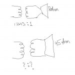
If you know your turns ratio and one of the Impedances then it is simply the Turns Ratio squared times the known impedance gives you the reflected impedance on the other side of the transformer.
This is given in post #7 under impedance ratio.
The example in your drawing is solved by 12.43(ratio)^2 * 8 ohms=1236 ohms(reflected primary impedance)
jer 🙂
This is given in post #7 under impedance ratio.
The example in your drawing is solved by 12.43(ratio)^2 * 8 ohms=1236 ohms(reflected primary impedance)
jer 🙂
The Speaker.
The 8 ohms is the speaker impedance.
And it is reflected to the opposite winding as 1236 ohms.
jer 🙂
The 8 ohms is the speaker impedance.
And it is reflected to the opposite winding as 1236 ohms.
jer 🙂
so 1236 = 12.432^2 * 8
Hence if the speaker is replaced by 45 ohm speaker
1236 = X^2 * 45
So X = Sqrt(1236/45) = 5.24
So Turns Ratio fo my transformer sould be 5.24 :1
is this correct to keep the Primary impedance same?
Hence if the speaker is replaced by 45 ohm speaker
1236 = X^2 * 45
So X = Sqrt(1236/45) = 5.24
So Turns Ratio fo my transformer sould be 5.24 :1
is this correct to keep the Primary impedance same?
Yes, Exactly!! 🙂
But keep in mind that the transformers primary is designed for 500 ohms at 200mW and not 1200 ohms at 200mW.
This means that the maximum voltage swing going into the primary winding should not go above 10Vrms for the lowest frequency of 300hz.
Unlike the one you have right now that can take 15.49Vrms at 300Hz for 200mW of input power.
Technically when using the newer one your lowest frequency should be limited to 465Hz if you want the full 200mW of output to your speaker.
This may or may not be an issue and you won't know until you try it.
But for the most part it shouldn't be any thing to worry about, as I am just trying to explain to you a little theory and as to why you might have some distortions if it does occur.
jer 🙂
Th
Now i understand the calculations but however I cant find the 500 ohms? Thank you 🙂
Q1
Where did you get that value ?
The datsheet shows 200mW Max output.
Where is the 500 ohms ?
Q2
So from the datasheet are you suggesting that I need a turns ratio of 5:1 where the primary impedance is 1200 ohms?
I dont see nay that matches this criteria?
Q1
Where did you get that value ?
The datsheet shows 200mW Max output.
Where is the 500 ohms ?
Q2
So from the datasheet are you suggesting that I need a turns ratio of 5:1 where the primary impedance is 1200 ohms?
I dont see nay that matches this criteria?
From the data sheet!!
http://www.mouser.com/ds/2/449/XC-600134-205894.pdf
On the 42TM026-RC that Sreten mentioned to use.
Correct there isn't one that matches your criteria.
That it is what I had said in the First place.
Sreten suggested that the 42TM026 might work and I went on to explain what to expect. 😉
jer 🙂
http://www.mouser.com/ds/2/449/XC-600134-205894.pdf
On the 42TM026-RC that Sreten mentioned to use.
Correct there isn't one that matches your criteria.
That it is what I had said in the First place.
Sreten suggested that the 42TM026 might work and I went on to explain what to expect. 😉
jer 🙂
That was the list I found from mouser.
Wouldn't there be another transformer which matches the criteria or its not possble.
From SRETEN QUOTE
"Of the listed transformers 42TM026-RC would work the best
with 45 ohm. It would allow about 6dB more maximum output.
5R output resistance will work with 45R (how they work out
it is suitable for 16 ohm is beyond me) "
Can you tell what does he mean by 5R and 45R?
And why 026 will be the best and how did he get 6dBvalue?
- Status
- Not open for further replies.
- Home
- Design & Build
- Construction Tips
- Replacing Audio transformer on a circuit