A search didn’t reveal my exact question, so here I am looking for affirmation and/or advice.
My Lafayette stereo PP 7189 amp now has a bad pwr xfmr primary winding. A variac has shown anything over 35-40V blows the fuse.
Since this proprietary xfmr is unobtainium, the closest thing I’ve found is a Fender Deluxe P-TF41316 replacement:
Primary 117 V, 60 Hz
Secondary 330-0-330 VAC @ 120 mA, 340 VDC @ 120 mA, with 50 V bias tap
Filament Winding 6.3 V, 3 A
Rectifier Filament 5 V, 3 A
The Lafayette 15-7 specs were:
Primary 117 V @ 1.1A
Secondary 680 VCT @ 120 mA, with 26V bias tap @ 1 mA
Filament Winding 6.3 VCT, 2.8 A
Rectifier Filament 5 V, 1.9 A
3% less rectifier voltage appears to be still adequate?
If I swap the stock 2.2K bias resistor for a 5K should drop it down to the schematic’s -16V
The filament and rectifier specs are sufficient, but the Fender replacement has no CT. I’ve read you can create a center tap by soldering two series-connected 100 ohm resistors between the X and Y filament wires, and their junction is grounded to the same terminal as the Sec 1 winding CT wire (red/yellow). Do I have this right?
Any feedback is greatly appreciated.
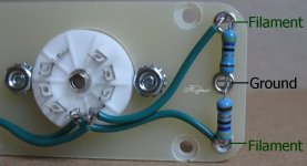
Yes, that should be fine.. For longevity I would use at least 1/2W resistors, 5% 1/2W metal oxide or carbon film types are suitable.
Thanks for the descriptive pic. If those bands are yellow, blue, black, gold x .1, then those are 46 ohms, less than half of the recommendations I've seen.
That segues to another thing I read, is that you should account for the additional current draw this will impose on the primaries. If it's a concern, I don't know what the primary current rating is with the Fender replacement, so might that be a problem?
That segues to another thing I read, is that you should account for the additional current draw this will impose on the primaries. If it's a concern, I don't know what the primary current rating is with the Fender replacement, so might that be a problem?
Two 46 Ohm resistors provides a 96 Ohm load on the 6.3V filament transformer.
6.3V/96 = 68.5mA (not very much current).
Even the little 12AX7, 12AU7, and 12AT7 filaments wired for 6.3V each draw 300mA per tube.
Two 46 Ohm resistors is OK.
Caution:
If the original 5V rectifier secondary had a center tap, and if that center tap was connected to the B+ circuit, then . . .
You can use a couple of 50 Ohm 5 watt resistors, connect them to the filament ends, and connect the other ends together. Then connect the center of those two resistors to the B+ filter where the old center tap was connected before.
Do NOT connect the junction of those two resistors to ground.
Last edited:
No CT on the 5V, neither old nor new xfmr.
Ordered the new xfmr plus resistors. Since the new xfmr is a bit smaller than the original, I need to make an adapter plate. Will follow up with results.
Thanks again for the help!
Ordered the new xfmr plus resistors. Since the new xfmr is a bit smaller than the original, I need to make an adapter plate. Will follow up with results.
Thanks again for the help!
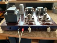
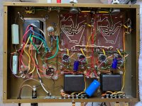
Got her singing again!
So I finally got around to wiring up the new PT (spec'd for a Fender Deluxe).
As it had a 50V bias tap versus the stock 26V, and having to make an artificial filament center tap with 100R resistors, it took another 9KR in series to get the control grid voltage back down to -15V. With smaller resistors, like 4.7K or 5.1K, it was around -26 or -24 and VERY distorted sound. Once I added a 3.9K to the 5.1K, the sound cleaned right up and now the bias pot (added by shop I purchased this amp from in order to use any brand of EL84 or 7189) is in mid-travel, giving lots of room for adjustment to a different output tube.
As it was before the original PT went bad, I can't believe the clean and full frequency range this little 1959 amp presents. I wonder how many speakers from that era even had the playback range to exploit this amp's capabilities, especially the highs.
Attachments

Genuine 7189 equivalents are not a problem. The Russian 6Π14Π-EB (6p14-ev), AKA EL84M, meets the need.
Have you measured the voltages being applied to the O/P tube plates and screen grids? Be very cautious about anything other than the 6Π14Π-EB in the unit. For instance, "reissue" "Gold Lion" N709s exhibit excellent sonics, but will not tolerate abuse. Fortunately, the 6Π14Π-EB exhibits quite decent sonics.
Have you measured the voltages being applied to the O/P tube plates and screen grids? Be very cautious about anything other than the 6Π14Π-EB in the unit. For instance, "reissue" "Gold Lion" N709s exhibit excellent sonics, but will not tolerate abuse. Fortunately, the 6Π14Π-EB exhibits quite decent sonics.
Thanks for the input, so I took some more measurements today.
Since this had the added bias trim pot, I adjusted it to get the control grids at the -15V spec, so this was my reference for all measurements. Also, the adjustment brought the -16V spec source an actual -15.42V.
With Sovtek EL84:
Pin 2: -15V
Pin 3: .150-.175V range of 4 tubes
Pin 4,5: 6.3VAC, -15.4VDC
Pin 7: 420V, spec is 435V
Pin 9: 342V, spec is 360
Current draw: 14.7mA, 14.8mA, 16.4mA, 17.5mA
I then swapped in a quad of Reflektor 6N14N-EP:
Pin 2: -15V
Pin 3: .180-.215V range of 4 tubes
Pin 4,5: 6.3VAC, -15.4VDC
Pin 7: 415V, spec is 435V
Pin 9: 341V, spec is 360
Current draw: 18.1mA, 18.9mA, 20mA, 21.5mA
Is it correct to assume the lower measured pin 7 & 9 voltages are due to the new PT being 330-0-330, versus original 340-0-340?
Attachments
You should tie your new transformer to your adaptor plate by all it's four screws.
Best regards!
Best regards!
Good catch! I lost one of the nuts and need to stop by the hardware store.
I was expecting to hear something like, "My six-year-old could solder better than that." 😱
I was expecting to hear something like, "My six-year-old could solder better than that." 😱
- Home
- Amplifiers
- Tubes / Valves
- Replacement xfmr has no filament CT