May as well. That seller is telling you that he does not expect the amp to work and lied about its construction. You can see the PCB attachment screws in the picture below.I think you know better than the ebay seller, too bad it is washington and the shipping to me in canada is too much, $65US/~80+ cdn. I will keep an eye open for one closer to me.

p.s. I had a typo in the title of this thread. It should be Sherwood (not Shearwood).
Last edited:
Thx for the pic, Shearwood 🙂
Already had the service manual, not sure why, could have used it to help someone fix one here or on AK at one time. I did notice it has the floating complementary jfets, push pull VAS, latfets might be another reason.
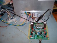
Did up the Bob Cordell DH-220C re-design of similar topology and used a couple of dual die Alfets for my testing. It is a very fast amp. Design uses Linear Systems complementary jfets.
The design is looking for a chassis.
Already had the service manual, not sure why, could have used it to help someone fix one here or on AK at one time. I did notice it has the floating complementary jfets, push pull VAS, latfets might be another reason.
Did up the Bob Cordell DH-220C re-design of similar topology and used a couple of dual die Alfets for my testing. It is a very fast amp. Design uses Linear Systems complementary jfets.
The design is looking for a chassis.
Attachments
Last edited:
I think the eBay seller refers to these. Which are a bit, as Dave would say, how-ya-doin' but small alu heatsinks are hardly "heavy"
dual source resistors look funky too.
The amp uses some very unique Toshiba and Hiatchi semis.
I could not find a pic of the main ecaps in my search.
The amp uses some very unique Toshiba and Hiatchi semis.
I could not find a pic of the main ecaps in my search.
Last edited:
You may be right. The 2SA968Y/2SC2238Y are very popular driver transistor pair in TO-220 package. But the small heatsink is not heavy enough to cause it to break loose. On the other hand, the Inkel (Korean manufacturer of this amp) should have drilled the heatsink hole higher so that its base will rest on the PCB like the picture bleow.I think the eBay seller refers to these. Which are a bit, as Dave would say, how-ya-doin' but small alu heatsinks are hardly "heavy"View attachment 766999
The 2SA968Y/2SC2238Y pair are inexpensive and easy to get. If repair is needed, I will recommend replacing them with proper heatsink.

Last edited:
The Sherwood S-6040CP is almost 30 years old. The chassis construction is one of the sturdiest from that era, yet the layout is simple enough for DIYers. (I am more reluctant to attempt repairing an Adcom or Parasound.) The bottom plate is a 2 pieces design. Removing the front bottom plate allows access to the lower side of the amp driver and power supply boards.Be easy to fix. I think I would address that while I had it apart.
The Sherwood S-6040CP is not a Bryston, nor does it sound like one. The sound quality is at the level of a MOSFET Adcom or Parasound. It is worth keeping it going.
The service manual has good instruction on zeroing output DC and bias current adjustment. The information on repair is generally adequate, but not as comprehensive as it could have.
What was the specific issue you would like to correct, but didn't?
Last edited:
The Hitachi power MOSFET are difficult to find. Even if you do, it will cost an arm and a leg. They are 140V/8A devices in the Sherwood. With 2 pairs each per channel and a large heatsink, the Sherwood S-6040CP should last for a while.dual source resistors look funky too.
The amp uses some very unique Toshiba and Hiatchi semis.
I could not find a pic of the main ecaps in my search.
Audio (Lateral) MOSFET's for Class AB - Overview, P-Spice URL's
It is discussed in the posts above, with photos, a potential improvement wrt the heatsinks on the driver transistors. Actually you yourself suggested it so I'm not sure what you're confused about [emoji23]The Sherwood S-6040CP is almost 30 years old. The chassis construction is one of the sturdiest from that era, yet the layout is simple enough for DIYers. (I am more reluctant to attempt repairing an Adcom or Parasound.) The bottom plate is a 2 pieces design. Removing the front bottom plate allows access to the lower side of the amp driver and power supply boards.
The Sherwood S-6040CP is not a Bryston, nor does it sound like one. The sound quality is at the level of a MOSFET Adcom or Parasound. It is worth keeping it going.
The service manual has good instruction on zeroing output DC and bias current adjustment. The information on repair is generally adequate, but not as comprehensive as it could have.
What was the specific issue you would like to correct, but didn't?
Last edited:
If it is NOT broken, don't fix it.It is discussed in the posts above, with photos, a potential improvement wrt the heatsinks on the driver transistors. Actually you yourself suggested it so I'm not sure what you're confused about [emoji23]
I don't see the recap job as simple, but it is necessary for my amp. The driver transistors are working fine as is. But Inkel could have done a better design.
If it was me doing it, I would [emoji1] what you do is up to you, that's your call, it's your amp!
I hope your amplifiers give you many more years of service, and happiness, as I'm sure they will.
I hope your amplifiers give you many more years of service, and happiness, as I'm sure they will.
The thought of repositioning the driver transistor heatsinks did come across my mind. But the chassis side panel is too high to allow easy access to the HS mounting screws. It means that I have to de-solder the driver to do it. I decided against it.If it was me doing it, I would [emoji1] what you do is up to you, that's your call, it's your amp!
I hope your amplifiers give you many more years of service, and happiness, as I'm sure they will.
Which version of the Cordell design? I am not familiar with the "dual die Alfet". I assume they are 2 power FET in a single package.Thx for the pic, Shearwood 🙂
Already had the service manual, not sure why, could have used it to help someone fix one here or on AK at one time. I did notice it has the floating complementary jfets, push pull VAS, latfets might be another reason.
Did up the Bob Cordell DH-220C re-design of similar topology and used a couple of dual die Alfets for my testing. It is a very fast amp. Design uses Linear Systems complementary jfets.
The design is looking for a chassis.
I am a big fan of Bob Cordell since I started reading his writing on the pages of Audio Magazine in the 1980's. The last time I build an audio amplifier from scratch was James Bongiorno's Ampzilla from the Popular Electronic. I was in graduate school then and was able to take advantage of the research lab shops to make the PCB and the chassis. The best part of that experience was being able to curve-trace, select and match all the small signal transistor pairs.
Power Supply Board recap
I removed the old power caps. There is no brand name on it except a small triangular symbol. Anybody recognize it? I guess that it may be the Mitsushita trade mark.


The terminal pattern look very similar to the Panasonic cap I ordered from DigiKey.
The pictures show the power supply board before the cap removal.


And after the caps were removed.


The cap removal took some effort, but not particularly difficult. The leads (4 per cap) were bent before soldering. A de-soldering tool with strong suction is recommended. Care is required to avoid damaging the PCB. The cap were glued down with some rubber glue on the component side.
I removed the old power caps. There is no brand name on it except a small triangular symbol. Anybody recognize it? I guess that it may be the Mitsushita trade mark.
The terminal pattern look very similar to the Panasonic cap I ordered from DigiKey.
The pictures show the power supply board before the cap removal.
And after the caps were removed.
The cap removal took some effort, but not particularly difficult. The leads (4 per cap) were bent before soldering. A de-soldering tool with strong suction is recommended. Care is required to avoid damaging the PCB. The cap were glued down with some rubber glue on the component side.
Nice notes. Yes that's the old Matsushita logo. Shows up a lot in Japanese gear of that vintage.
Replacement caps arrived

It looks like twins of the original, same case dimension and same terminal pattern and pitch. No drilling of new holes!!! (ubergeeknz, you are a wonderful resources for us.)


I hope to get it all done tomorrow, but will do it slowly and deliberately to avoid mistake and error.
The 12 pieces of Panasonic ECE-T1JP183EA, 18,000uF/63V, arrived today. DigiKey shipped it in double box, very well protected.Wow, that is exactly what the doctor orders. The Panasonic has the exact can diameter as the current cap. Yes, I need to order 12 to get the price break.
The Kemet is larger in can diameter, but may still fit. But there is no reason to go with the Kemet for its higher price.
I really appreciate your effort to do the search for me and found the exact item that I need, with the bonus of higher capacitance.
It looks like twins of the original, same case dimension and same terminal pattern and pitch. No drilling of new holes!!! (ubergeeknz, you are a wonderful resources for us.)
I hope to get it all done tomorrow, but will do it slowly and deliberately to avoid mistake and error.
Practically porn. Finding an excellent match at a reasonable price is a great outcome [emoji4] I look forward to seeing the finished product.
Finishing the job
After a 2 days delay, I finally found time to do it. Total time is about 2 hours. I did it slowly to make sure the polarity are correct. The power caps have "no-connect" mounting pins that help the polarity ID.
I also replaced 6 electrolytes that are on the power supply board. (C307. C308, C309, C310, C401, C402)
On the PCB, all these and the 4 large power caps were glued to the board with some rubber glue. I did not use the glue. Each of the power cap has a small rubber block on top and underneath the PCB. I carefully peered them off for reuse. I glued them back using 3M spray adhesive.


I took a 1 hour break for the adhesive to dry and clear my head before I double check for unwetted soldering joints. When it looked good, I closed the bottom plate. Flapped it over and plugged it in. No smoke, no spark so it is good. I powered it up. The LED came on and the relay clicked a few seconds later. I will warm it up for 6-10 hours before I check general voltage, idle current and DC offset.


After a 2 days delay, I finally found time to do it. Total time is about 2 hours. I did it slowly to make sure the polarity are correct. The power caps have "no-connect" mounting pins that help the polarity ID.
I also replaced 6 electrolytes that are on the power supply board. (C307. C308, C309, C310, C401, C402)
On the PCB, all these and the 4 large power caps were glued to the board with some rubber glue. I did not use the glue. Each of the power cap has a small rubber block on top and underneath the PCB. I carefully peered them off for reuse. I glued them back using 3M spray adhesive.
I took a 1 hour break for the adhesive to dry and clear my head before I double check for unwetted soldering joints. When it looked good, I closed the bottom plate. Flapped it over and plugged it in. No smoke, no spark so it is good. I powered it up. The LED came on and the relay clicked a few seconds later. I will warm it up for 6-10 hours before I check general voltage, idle current and DC offset.
After running idle for 8 hours, the DC offset and bias current are both within spec without touching the trim pots.
The power output stage rails are 54.6 volts plus/minus against a spec of 54 volts. The voltage amplifier stage calls for 61.0 volts plus/minus. It measures 59V plus and 58.6V minus.
I leave it plugged in running idle for another 12-14 hours. If the above measurement do no change significantly, I will put it back to the system and declare victory. If it sounds good, I may not come back to measure noise and THD until later this summer.
This is the oldest of 3 Sherwood S-6040CP I have. I will finish recap the other 2 soon. The first experience is very positive and the process is enjoyable.
- Status
- Not open for further replies.
- Home
- Amplifiers
- Solid State
- Replacement power electrolytic: Shearwood S-6040CP amplifier