Are the pops still present?
Are you able to unplug connector J701 to interrupt audio into power amp? If so, short pins 1 and 2 to ground input to PA and look for improvement versus continuing same issue.
I assume that’s left channel, but did not verify.
Disconnected from J701 socket, have to short J701 socket pins how? socket pin1(L) to socket pin2(ground) ?
I noticed the connector wiring is symmetrical. You might be able to swap left/right if cable length and keying allow.
Otherwise, pin 1 short to pin 2.
Otherwise, pin 1 short to pin 2.
Did you short the inputs to ground?Disconnected from J701 socket.
If yes then next step would be to replace all the smaller lytics on the power amplifier board and see if the noise still remains.
Resoldering the whole board would also be of benefit.
Attachments
Tried to short pin1 to pin2 with metal key just for testing purposes on J701 socket, but it throw some loud pops and cracks to speakers so I stopped doing it. Or should I turn this device off, and then short pin1 to pin2 using some wire instead of key that is already grounded by my hand? and then turn it on again?
Never poke around in signal path when amplifier is powered on (unless you know exactly what you are doing) - you may initiate oscillation and fry your outputs (been there, done that).Or should I turn this device off, and then short pin1 to pin2
When shorting something you turn the power off and solder a wire jumper in place.
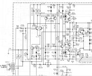
BUT there seems to be something strange with the schematics - pins 2 and 3 (in connector J701) do not seem to have ground connection on the board.
If it is not a mistake in the schematics then when disconnecting the cable from J701 will leave the "ground" of the input stage "in the air".
You need to verify what is the exact situation in your amplifier before proceeding.
Sorry, missed the obvious - 10R resistors R705/706 to ground. Hard to believe that they would become noisy but replacing them is cheap...pins 2 and 3 (in connector J701) do not seem to have ground connection on the board.
Have you checked all the voltages as indicated in the SM and have you measured the values (one unsoldered leg) of the two resistors R859 and R860, it is a classic on this model.

Pin1 should be left, pin2, pin3 ground and pin4 should be rightNever poke around in signal path when amplifier is powered on (unless you know exactly what you are doing) - you may initiate oscillation and fry your outputs (been there, done that).
When shorting something you turn the power off and solder a wire jumper in place.
BUT there seems to be something strange with the schematics - pins 2 and 3 (in connector J701) do not seem to have ground connection on the board.
If it is not a mistake in the schematics then when disconnecting the cable from J701 will leave the "ground" of the input stage "in the air".
You need to verify what is the exact situation in your amplifier before proceeding.
If J701 socket doesnt have ground, then i have to connect these socket pin1 and pin2 to the other endpoint ground?
Last edited:
Have to take this board out, then keep in powered on, and then measure voltage?Have you checked all the voltages as indicated in the SM and have you measured the values (one unsoldered leg) of the two resistors R859 and R860, it is a classic on this model.
View attachment 1290076
yesHave to take this board out, then keep in powered on, and then measure voltage?
no, this card generates the different voltage regulations, so you can measure the voltages at their routing points directly where the cords arrive on the other PCBs.
At Marantz in general, if you look on the PCB at the arrival of each connector, you have the voltages which are indicated and of course, you use the SM to see who goes where and who comes from where.
but start by taking out this card, checking these two resistors, checking the soldering and if you are equipped to check them, the capacitors.
It's one of the rare Marantz of this era which is acceptable and which certainly doesn't have that damn STK 31xx, it would be a shame not to try to repair it.
Okay so i have to take this board out, remove these resistors from board and measure them value? Then unsolder capacitors and take a LCR meter and check them too?
Will also make this special connectable wire to route J701 socket pin1 to J601 socket pin2(as there should be that ground that J701 pin2 didnt have)
Will also make this special connectable wire to route J701 socket pin1 to J601 socket pin2(as there should be that ground that J701 pin2 didnt have)
I would just replace these 10R resistors and all lytics on the board.
Then disconnect the cable from J601 and jumper pins 1/2 and 3/4.
The noise might disappear - if not then more work lies ahead.
Then disconnect the cable from J601 and jumper pins 1/2 and 3/4.
The noise might disappear - if not then more work lies ahead.
- Home
- Amplifiers
- Solid State
- Replacement for Marantz PM80 MKII: (PM7001/7200 vs. Rotel RA-02/04/05 vs. NAD C352)