Update:
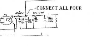
I spoke with Cary tech support and they recommended adding a 10uf 600v cap and a 20 ohm 10 watt resistor in the configuration seen in the attached pdf. Will this solve the problem since the recitfier now sees only 10uf without compromising tone or dynamics? FWIW, I ordered a poly Clarity Cap (630V) instead of an electrolytic and a Mundorf power resistor to facilitate repair. I'll find a way to cram them in there as they are fairly large componenets.
Thanks for any tips or advice in advance.
Attachments
Last edited:
If that is a monoblock the 20 Ohm resistor only needs to be 2W not 10W as two 6L6s won't draw 200ma and 200mA thorugh a 20 ohm resistor is only 0.8W. If the power supply drives two amps I'd go with a 5W resistor.
Second, the first jump over from the 20 ohm resistor to the 0.22uF should be a connect to the 1200uF 450V cap or you have no B+ to the transformer center tap.
Second, the first jump over from the 20 ohm resistor to the 0.22uF should be a connect to the 1200uF 450V cap or you have no B+ to the transformer center tap.
FWIW, this Cary is a stereo amp using EL34's.
Please excuse my lack of theory here but I'm not sure I understand your second statement. The resistor will connect to the red wire currently in pin 8 that will be desoldered from the socket pin. Both the resistor and cap are then tied to pin 8. The cap is tied to ground and again, the resistor connects to the red wire that should be going out to the first filter cap. Doesn't this ensure that the resistor is immediately connected to the first filter cap? Thanks.
Please excuse my lack of theory here but I'm not sure I understand your second statement. The resistor will connect to the red wire currently in pin 8 that will be desoldered from the socket pin. Both the resistor and cap are then tied to pin 8. The cap is tied to ground and again, the resistor connects to the red wire that should be going out to the first filter cap. Doesn't this ensure that the resistor is immediately connected to the first filter cap? Thanks.
FWIW, this Cary is a stereo amp using EL34's.
Please excuse my lack of theory here but I'm not sure I understand your second statement. The resistor will connect to the red wire currently in pin 8 that will be desoldered from the socket pin. Both the resistor and cap are then tied to pin 8. The cap is tied to ground and again, the resistor connects to the red wire that should be going out to the first filter cap. Doesn't this ensure that the resistor is immediately connected to the first filter cap? Thanks.
He's right, as drawn it can't work. How could any power get to the center tap of the output transformer?
But this is easy. You MUST understand just a little theory, What you are building in the power supply is a CRCRCRC filter. This is really just a chain of CRC filters. A CRC filter is sometimes called a "pi" filter because it looks like the greek letter with to uprights and a bar across the top of them. In this case the top bar is a resister that connects the tops of two capacitors. te bottoms of the caps go to ground.
Read this. It explains how tube style power supplies work and keep to only high school level math The Valve Wizard
You will notice at the bottom is a schematic that looks a lot like yours. Read the above untill you understand it backwards and forwards.
BTW there was no need to buy a poly capastior, the electrolytic would do fine, may with a.01uf bypass. Nothing wrong with an over sized resistor, I buy them about 4X over rated so they run cool. 5W wirewond ceramic would be perfect but 10W dowes no harm and both sell for less then $1 so use what you have.
Thanks for raising the red flag here gents. I'll run this by Cary's tech support but in the meantime can someone instruct me on the proper way to install the cap and resistor?
What I don't understand is why the .22 cap is a concern. If you look at the pic I uploaded on a previous page in this thread, the .22 cap is just a bypass across the +/- of the filter cap that probably could be removed without much consequence or at least, I've been told. Why would this hook up now cause the CT on the xformer to not receive power? For some reason, I don't see this?
And thanks again for your time and for persevering with my lack of knowledge here. I just want to get this thing right and get back to listening to music.
I'll read over the link provided. Maybe I'll get lucky and actually understand what I'm reading.
The 0.22uF cap is not an issue.
What I was trying to point out is that the center tap of the transformer only connects to the top of the 1200uF cap. There is no source for current flow into the transformer. I suspect there should be a connection where there is a loop over wire from the 20Ohm ressistor to the 0.22uf Cap should connect to the 1200uF cap and line to the transformer center tap.
What I was trying to point out is that the center tap of the transformer only connects to the top of the 1200uF cap. There is no source for current flow into the transformer. I suspect there should be a connection where there is a loop over wire from the 20Ohm ressistor to the 0.22uf Cap should connect to the 1200uF cap and line to the transformer center tap.
Attachments
Last edited:
OK. Maybe the schematic isn't correct? Also, my amp is the 70A version, not the MKII. Similar but different. Cary doesn't have a schematic of this particular version I own unfortunatley.
Let me try to understand this again. The red wire currently connected to pin 8 of the rectifier is disconnected and the resistor is installed between pin 8 and the now disconnected red wire which currently ties to the filter cap. So this should be the same hook up as the original except with a 20 ohm resistor in between pin 8 and the red wire. Why would this suddenly be an issue? It's only a resistor. Or is it the cap hook up (also tied to pin 8 but tied to ground), that causes concern here?
Let me try to understand this again. The red wire currently connected to pin 8 of the rectifier is disconnected and the resistor is installed between pin 8 and the now disconnected red wire which currently ties to the filter cap. So this should be the same hook up as the original except with a 20 ohm resistor in between pin 8 and the red wire. Why would this suddenly be an issue? It's only a resistor. Or is it the cap hook up (also tied to pin 8 but tied to ground), that causes concern here?
I decided to add the 10uf cap only and it seems to be working great. It sounds "right" again! Anyone interested in Weber WV4 Copper Caps cheap? ;}
And for the first time since I've owned the amp, I can use the STB switch without the 2nd rectifier going ballistic.
Thanks for all your assistance and education. Very much appreciated.
And for the first time since I've owned the amp, I can use the STB switch without the 2nd rectifier going ballistic.
Thanks for all your assistance and education. Very much appreciated.
The 0.22uF cap is not an issue.
What I was trying to point out is that the center tap of the transformer only connects to the top of the 1200uF cap. There is no source for current flow into the transformer. I suspect there should be a connection where there is a loop over wire from the 20Ohm resistor to the 0.22uf Cap should connect to the 1200uF cap and line to the transformer center tap.
Sorry to get back to this but I have a question:
If I'm reading the schematic you supplied correctly, I would connect the R to pin 8 of the rectifier and then to the + side of the 1200uf cap which is in parallel with the .22 cap?
Although the amp has been absolutely stable since I added the 10uf cap, I'd like to do it right and add the resistor. Thanks.
- Status
- Not open for further replies.
- Home
- Amplifiers
- Tubes / Valves
- Replace Tube Rectifier With Weber CC?