OK here we go.
Disassemble the power adapter.
Usually You have a transformer 4 diodes (bridge) & a capacitor or perhaps a regulator or a transistor with zener after the diode bridge. I believe at that time they didn't make switchmode supplies.
Disconnect power & wait a few seconds.
Meter on Ohm scale measure primary & secondary trafo windings. Infinite ? trafo winding open. Both readings trafo OK.
Power it. Be careful not getting zapped.
Meter on AC scale. Measure the trafo output. Got reading ? Trafo probably Ok depending on voltage. No reading Trafo Kaputt. Is there a fuse ? Check.
Now in DC scale measure after the bridge. No reading diode kaputt (all 4 unlikely) or Capacitor shorted / dried (more probably). Reading Ok ? what's next after ? Cable. Measure jack . No reading ? cable is bad. Regulator or transistor ? measure after.... etc
Post a picture of the inside.
or just use the connector from bad adapter, cut it, and solder it to new adapter
observing polarity
observing polarity
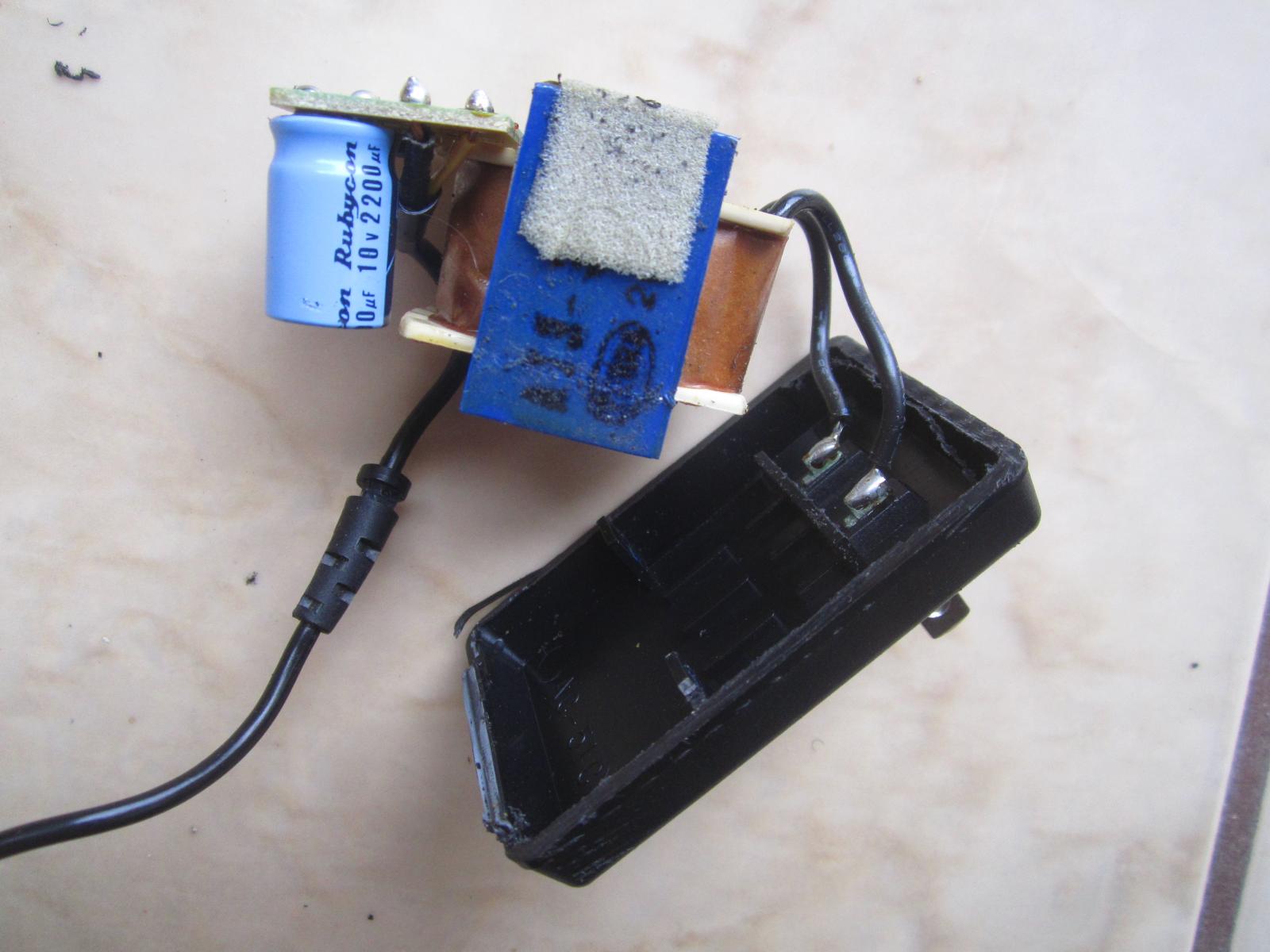
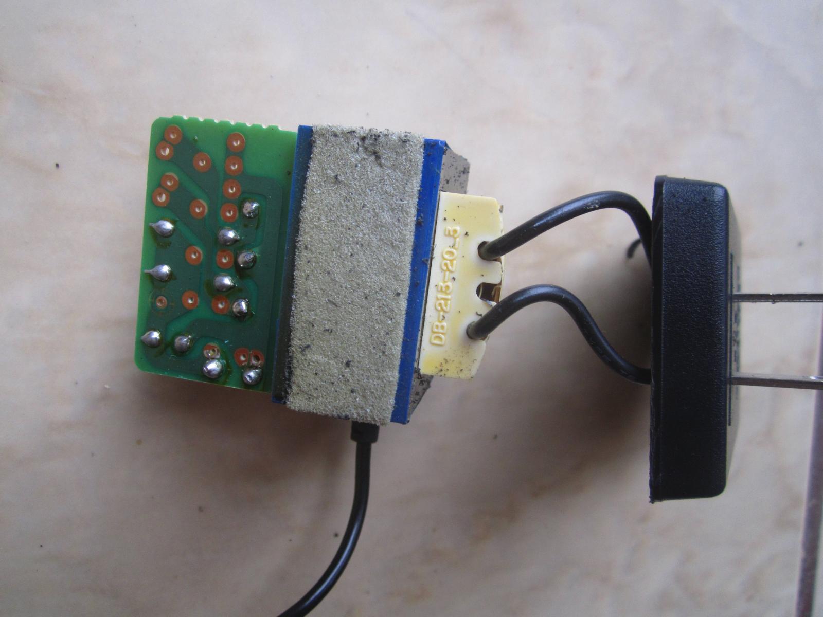
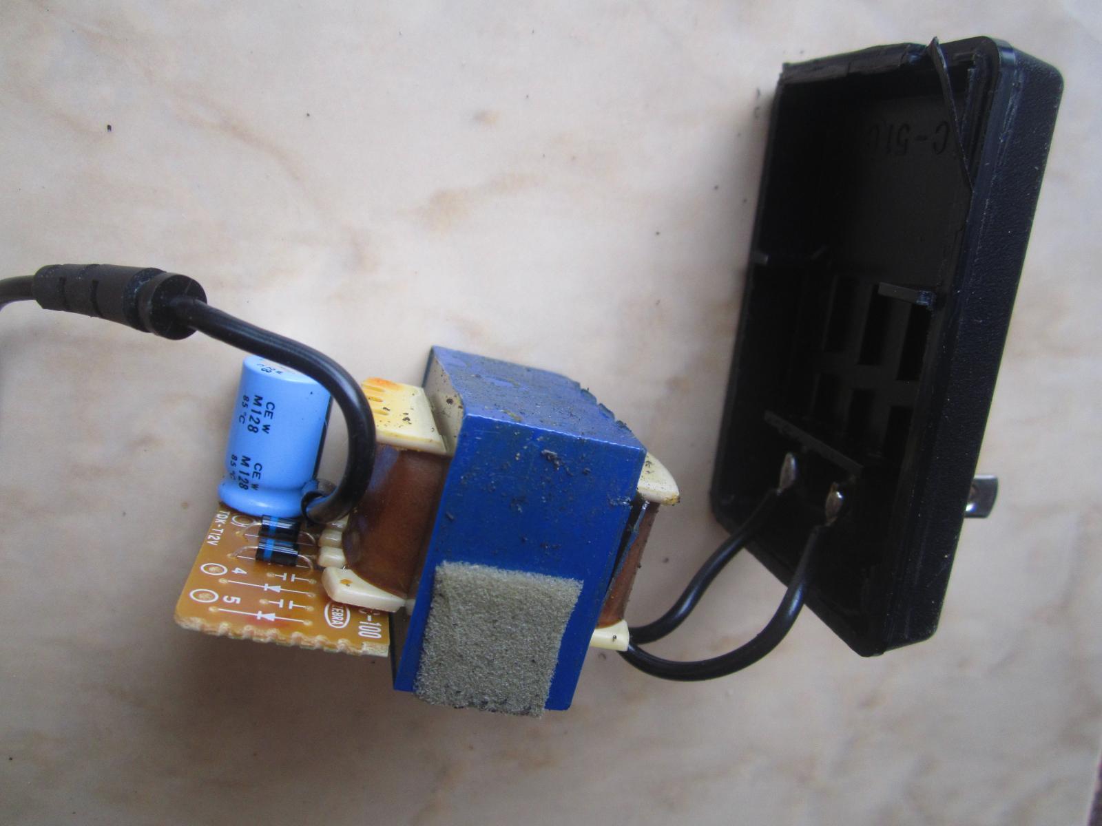
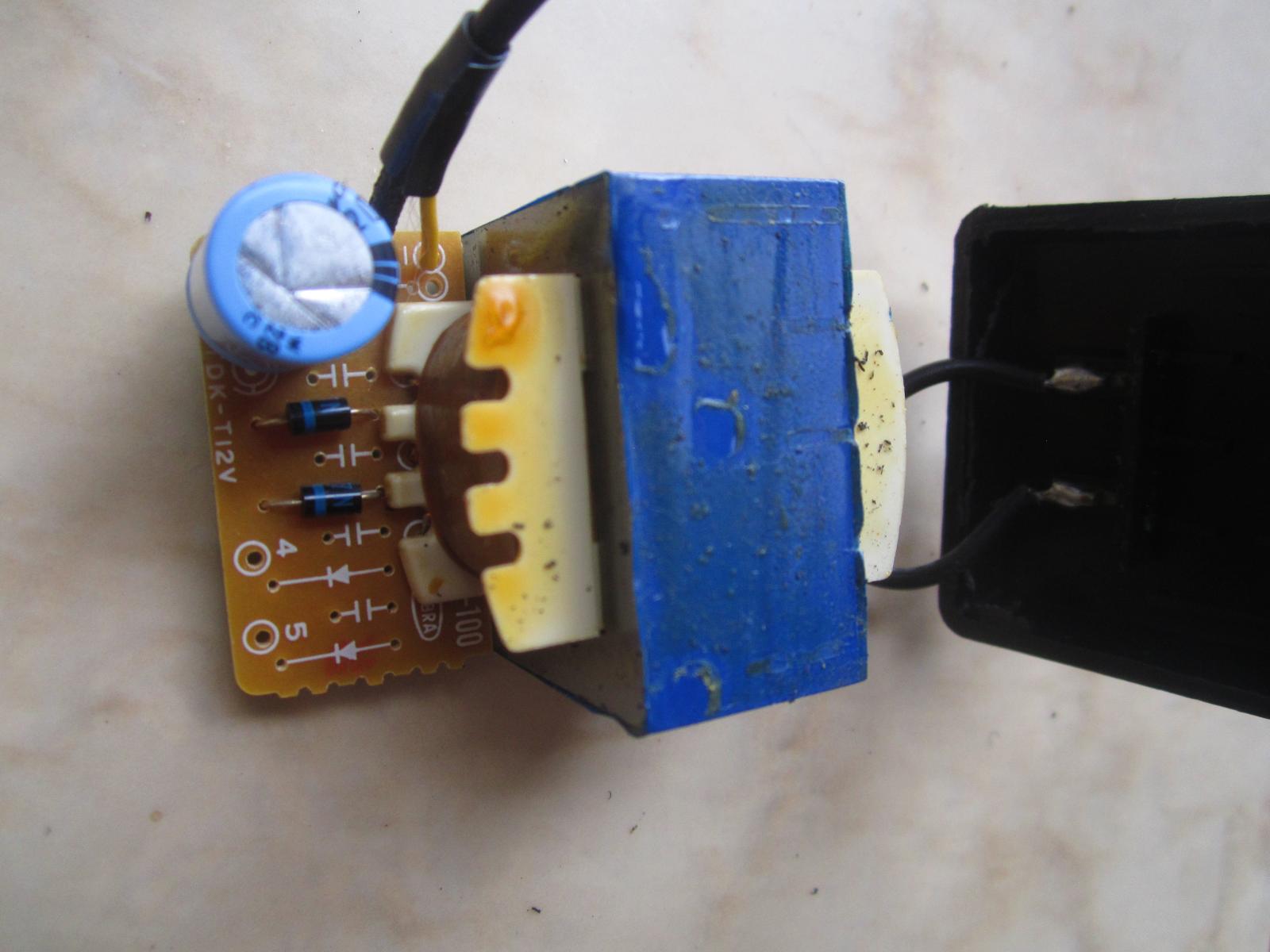
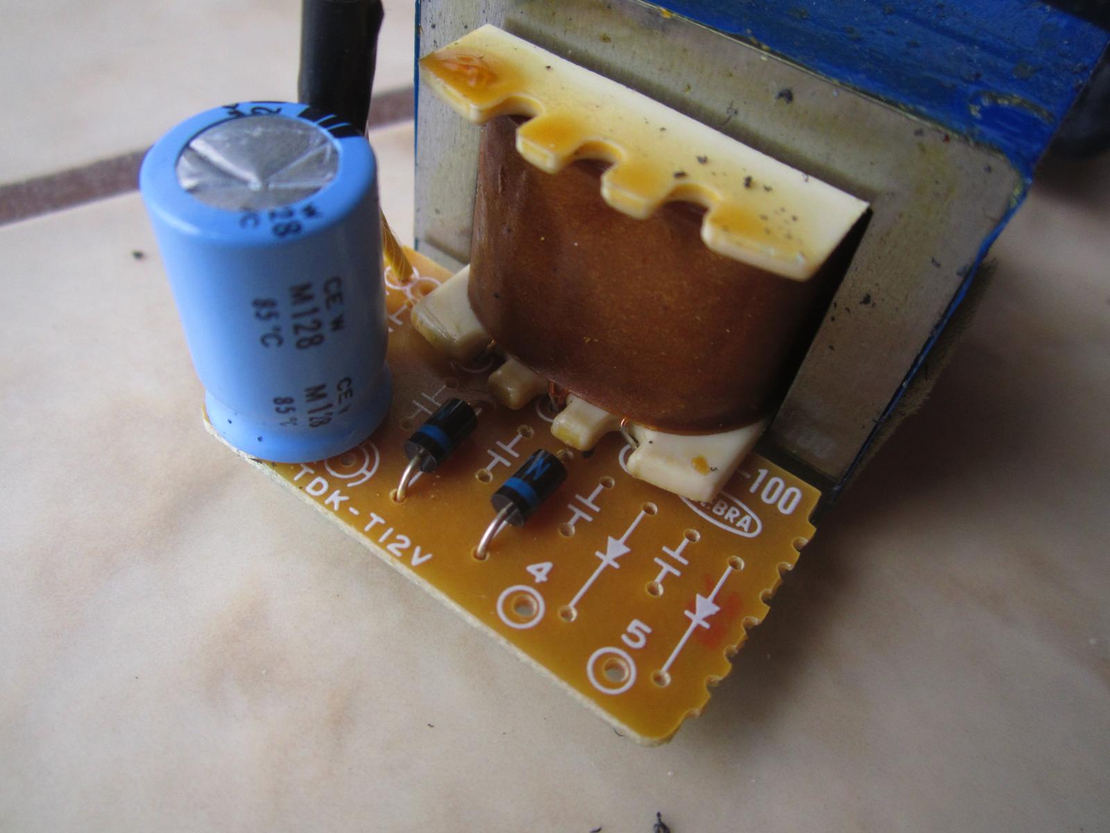
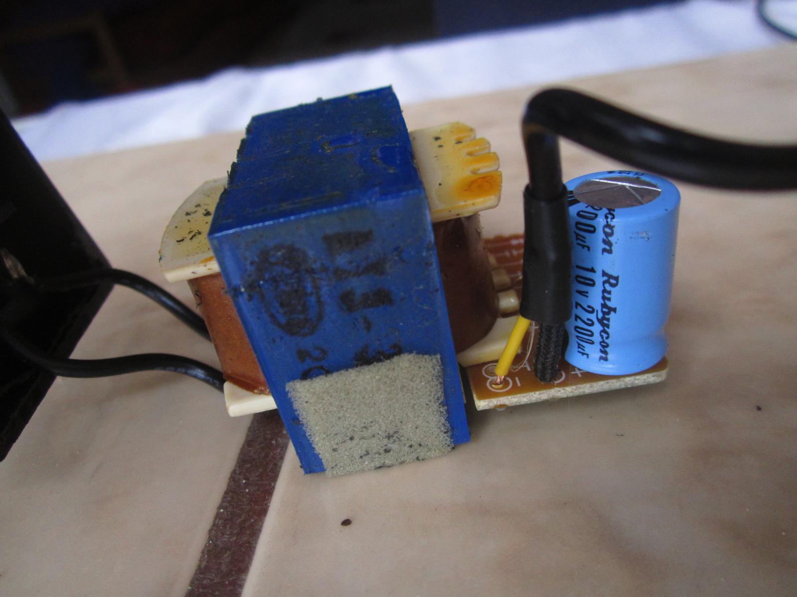
Here are fotos of the inside of the adapter.
Thanks for the detailed instructions - I don't know what the exact names are of individual components, but I can study up and try to suss it out.
Thanks for the detailed instructions - I don't know what the exact names are of individual components, but I can study up and try to suss it out.
My prime focus would be on the subject of this thread i.e. the cassette recorder itself.
There's little point expending time in repairing the power adapter at this stage if the recorder subsequently proves to be irrepairable!
I would simply insert 3 'D' cells and concentrate on investigating the cause of the recorder's speed instability.
Have you opened the recorder up to inspect the condition of the drive belts and pinch roller yet?
Just a thought - when was the last time you cleaned the pinch roller, capstan and tape heads?
He wants to learn, so I gave him some instructions.There's little point expending time in repairing the power adapter at this stage if the recorder subsequently proves to be irrepairable!
Funny is ...original was meant for a diode bridge but due to manufacturing costs..so let it be a half wave center tapped supply and let's hear some recorded hum.
I don't know what the exact names are of individual components
A basic supply:
A transformer 300-500mA I suppose.
Two black 1N4XXX diodes (4001 to 4007 work fine here)
A capacitor (With more capacitance to overcome the missing two diodes)
From the pictures I would bet on the transformer.
Have You measured the transformer Yet ?
but a PSU is always handy...
I have tons of them from HDD enclosures and they work fine with my AKG wireless mics when the cable breaks.
MAACO, I wasn't questioning your good intentions! 😎The wire and jack all seem OK.
However, I would suggest you check that Edward knows how to test the adapter lead for continuity before proceeding further.
He only says it 'seems' OK.
...Funny is ...original was meant for a diode bridge but due to manufacturing costs..so ....
I think the one PCB was used for *many* output voltages, for different products, with different transformer and rectifier.
Two diodes (in a quality product like this) suggests a FULL-wave center-tap. For lower voltages this may be more efficient: one diode drop instead of two as in a diode bridge. If this is 3 D-cells (4.5V) it is well into the range where lower diode drops balance a bridge's better iron utilization. A 12V supply might use a single winding and all four diode positions as a bridge.
So...doing my best to start learning how to fix this adapter - I assume "trafo windings" refer to TRANSFORMER windings.
1) I am trying to check for resistance (OHMs) between windings - as suggested. Problem, I can not figure out how to do this because the windings are wrapped in a kind of wax paper without any area of actual winding exposed. Is there a trick to doing this?
2) ...therefore currently also can not measure trafo output voltage.
3) can not see any fuse. All I see is a trafo, 2 diodes, and 1 capacitor.
4) I tested (OHMs) for continuity both the cable and the now removed end jack - and all test OK for continuity.
The plug that plugs into the wall, put your meter across the active and neutral and you should get a reading. First photo the 2 wires that are soldered to the back of the plastic case
Transformers have a thermal fuse in the primary winding and this goes bad. If it is open circuit there is your problem. What reading do you get.
Transformers have a thermal fuse in the primary winding and this goes bad. If it is open circuit there is your problem. What reading do you get.
Yes... testing the plug that goes into the wall, behind the plastic - I get 120V.
I can't figure out how to test the transformer itself -- there are no exposed coils or wires? Should I cut a small hole in the wax paper that surrounds the coils? --- and stick the probe thru that?
I can't figure out how to test the transformer itself -- there are no exposed coils or wires? Should I cut a small hole in the wax paper that surrounds the coils? --- and stick the probe thru that?
Edward, make sure your adapter is NOT plugged into the wall and powered up for the troubleshooting I am about to describe:
Set your multimeter to the resistance (ohms) scale then place the probes across the two wires that are soldered to the back of the plastic case, as was described by warrjon.
These two wires connect to the primary winding of the transformer. If the meter indicates an open circuit, the primary winding has a break in it, possibly due to an open thermal fuse located within the transformer primary windings.
In that case, the transformer would require to be replaced, which would not be cost effective in this case.
If you do get a resistance reading, report what it is back here and await further advice.
Whatever you do, do not stick your probes through the waxed paper!
So... I did it like this -
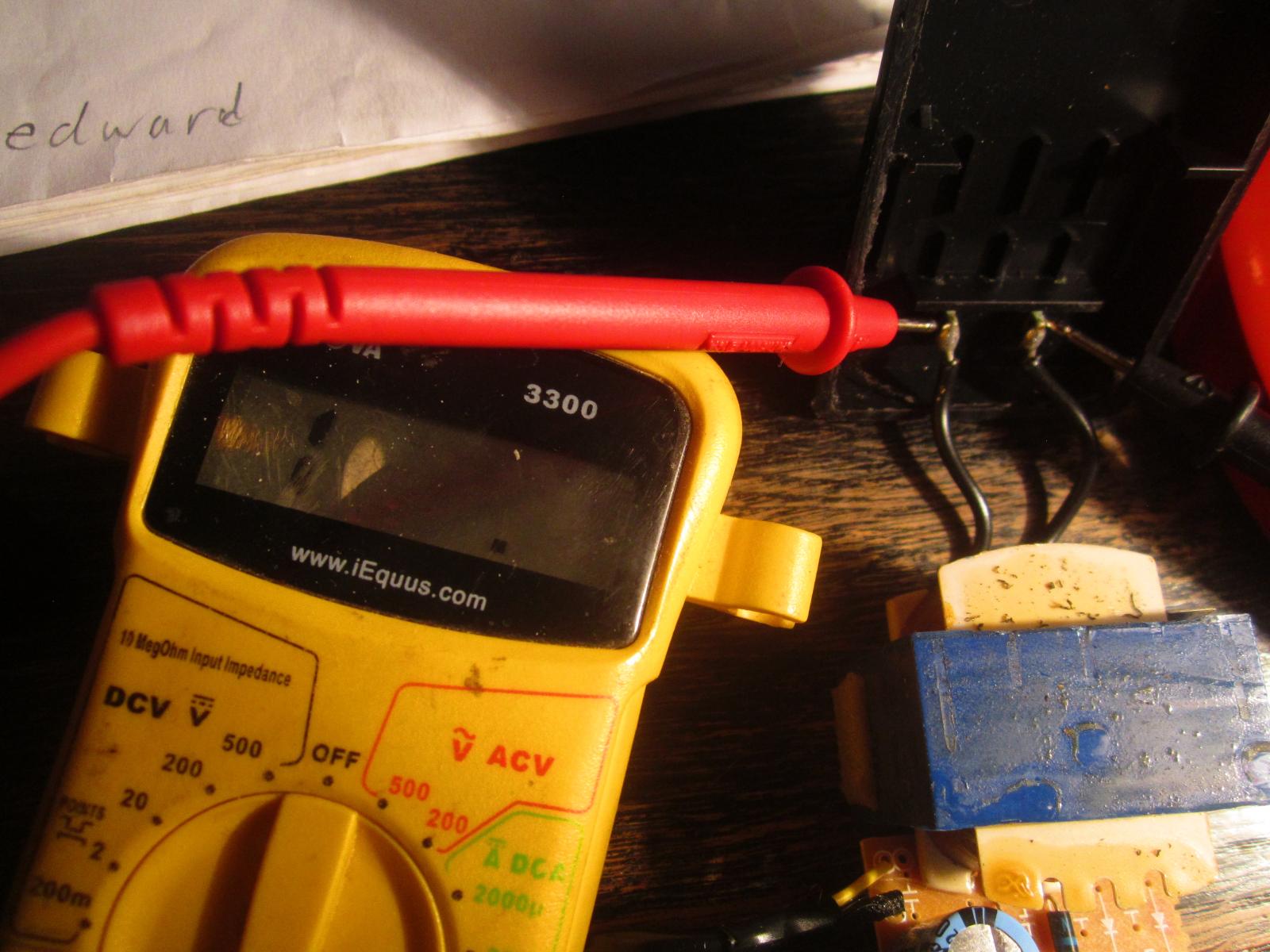
I hope I am reading on the correct spots.
I had the meter set at the lowest setting for OHMs (200), and there was NO READING whatsoever. I also tried at a higher OHMs setting and nothing.
When I touch the two probes together I get some activity on the meter, but on those PSU terminals the meter does nothing at all.
Is this good?
You are reading at the correct spots.
The result is not good - your transformer has given up the ghost!
I suggest you replace the entire adapter as replacing the transformer would not be cost effective.
Can't wait to start investigating the cassette recorder! 🙂
The result is not good - your transformer has given up the ghost!
I suggest you replace the entire adapter as replacing the transformer would not be cost effective.
Can't wait to start investigating the cassette recorder! 🙂
aha.... so the "nothing" reading means that there must be a complete break somewhere in the coil inside the transformer? Does the "nothing" reading mean the same thing as an "open circuit"?
Could the transformer be damaged because I used it quite a lot with a 240 >120 stepdown converter? Might this stress out small components like this?
Could the transformer be damaged because I used it quite a lot with a 240 >120 stepdown converter? Might this stress out small components like this?
Yes Edward - an open circuit - a complete break - just like when the meter probes are separated from each other by thin air!
The transformer would not be stressed in the way you suggest. The failure could just be down to the built-in thermal fuse ageing.
The transformer would not be stressed in the way you suggest. The failure could just be down to the built-in thermal fuse ageing.
The thermal fuse is not replaceable as it is embedded within the transformer primary windings and hence is inaccessible.
Please buy three 'D' cells for now, Edward!
Please buy three 'D' cells for now, Edward!
- Home
- Source & Line
- Analogue Source
- Repairing MARANTZ PMD420 cassette recorder