Hi All,
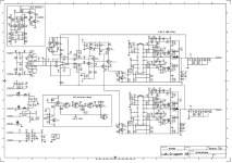
got e12:2 amp for repair. It was initially blowing fuses, SMPS easily fixed. Now, while checking I ran into issue where one channel is 30% quieter then other (pure sine pk-pk measured at output). Good channel is louder, just for reference. The amp is based on custom chip from infineon, irs20956, which is self oscillating digital amp. Chips are all good, swapped between channels with no effect. Supply voltages are all checked good, high-side and low side pins are showing the same AC and DC in both channels. So I am stuck with overall schematic, trying to get the reason why one channel is quieter. Both channels are BTL, which adds complexity to the measurements. Checking everything from input to output I found only one difference: ERR test point (pin 7 of IC202 opamp) shows clear input signal (1V pure sine, 1Khz) at 3,22V (pk-pk) ref to GND in working channel, while faulty channel has only 2,6V pk-pk there. Moreover, pins 5 and 6 are almost zero (AC) in working channel; faulty channel shows there input signal of 0,8V amplitude on each pin. I just dont understand why this difamp is there, what it is doing, and also q200/q201 circuit is weird. All this connected to NFB, so I am lost. Checked all trannies and diodes around, all checked good. No burnt resistors or other traces of fault. Any help appreciated.
got e12:2 amp for repair. It was initially blowing fuses, SMPS easily fixed. Now, while checking I ran into issue where one channel is 30% quieter then other (pure sine pk-pk measured at output). Good channel is louder, just for reference. The amp is based on custom chip from infineon, irs20956, which is self oscillating digital amp. Chips are all good, swapped between channels with no effect. Supply voltages are all checked good, high-side and low side pins are showing the same AC and DC in both channels. So I am stuck with overall schematic, trying to get the reason why one channel is quieter. Both channels are BTL, which adds complexity to the measurements. Checking everything from input to output I found only one difference: ERR test point (pin 7 of IC202 opamp) shows clear input signal (1V pure sine, 1Khz) at 3,22V (pk-pk) ref to GND in working channel, while faulty channel has only 2,6V pk-pk there. Moreover, pins 5 and 6 are almost zero (AC) in working channel; faulty channel shows there input signal of 0,8V amplitude on each pin. I just dont understand why this difamp is there, what it is doing, and also q200/q201 circuit is weird. All this connected to NFB, so I am lost. Checked all trannies and diodes around, all checked good. No burnt resistors or other traces of fault. Any help appreciated.
Attachments
Hi, did you find a datasheet for the irs20956 ? IR / infinion only seem to admit to irs20955 or irs20957 with the 7 being an improved 5. odd.
The major difference between IRS20956 and IRS20957 is the reference of its PWM input-- IRS20956, PWM input reference to -VCC, and IRS20957, PWM input reference to the ground.
I would say IRS20956 is generally different because of the internal oscillator vs external in 957