Hello all.
I have a used Vox Pathfinder 10 that has a strange issue, which I'm trying to repair. I've been trying a few fixes to no avail.
Description of the issue:
Other interesting information/things I've tried:
Results of poking around with oscilloscope+multimeter:
I also tried a strange (?) debugging method of probing the signal path with a line input, and listening to the output of that. If I 'listen' to the output of of U1A with an audio interface, it sounds okay on clean; same with output of U2A. Wasn't brave enough to try the drive channel, since the Vpp's are higher in that case.
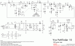
For reference, I'm using the schematic Rev E, traced and drawn by DM, corrections by Jan Flanders and "dimkasta" (found on imgur).
Any ideas?
I have a used Vox Pathfinder 10 that has a strange issue, which I'm trying to repair. I've been trying a few fixes to no avail.
Description of the issue:
- Clean channel has almost no output, unless the gain is all the way up (but with the gain all the way up like this, the sound is not clean at all; very 'farty' and fizzy almost like a strange digitized sound)
- Drive channel is severely distorted, but also mixed in with a strange fizzy sound. If gain is all the way up, there is a very audible, harsh buzzing sound even when not playing guitar.
Other interesting information/things I've tried:
- Problem occurs on both speaker and headphones.
- PCB looks good both top and bottom.
- Tried replacing the TDA2030; no difference.
- Same issues with different guitars and cables.
- Checked all solder joints; only one looked mildly poor; resolded that join (no difference).
- All caps look okay.
- I can 'shape' the noise using the bass/treb knobs, which indicates that the problem might come before the power amp stage.
- Noise goes away when guitar volume pot is turned down.
Results of poking around with oscilloscope+multimeter:
- Voltages on all op-amps are correct and clean.
- Output of first opamp (pin1 of U1) is in the ballpark of 150mVpp on both clean and drive when guitar lightly plucked.
- Output of second opamp (pin 7 of U1) is roughly 150mVpp on clean but much higher on drive (something like 4.7Vpp) when lightly plucked.
- Clipping LEDs light up as expected when on drive channel.
- Checked for earthing/grounding issues; can't find any. Low impedance path from chassis/ground planes/plug/etc. Amp plugged straight into well-earthed mains socket.
- Checked for good continuity between guitar-end tip of cable and PCB jack input.
I also tried a strange (?) debugging method of probing the signal path with a line input, and listening to the output of that. If I 'listen' to the output of of U1A with an audio interface, it sounds okay on clean; same with output of U2A. Wasn't brave enough to try the drive channel, since the Vpp's are higher in that case.
For reference, I'm using the schematic Rev E, traced and drawn by DM, corrections by Jan Flanders and "dimkasta" (found on imgur).
Any ideas?
Last edited:
Posting the schematic or a link to the schematic here is a nice thing to do. Just glancing at the Rev B on "aggh" it sounds like a bad capacitor in the signal path to me. When you say they "look" OK, does that mean that you pulled and tested/replaced them?
If not: I see most of the caps are poly, so they should be bullet proof. The only electrolytics I see that would be my first suspects are C8? the 2.2uF right after U1B, also C13 10uF, C21 22uF. Best to just replace them if you can.
After that, if the problem is still there, if the pots are not scratchy, and the drive switch not flaky, and you don't have a thin cracked solder joint somewhere, I'd replace the op-amps. JRC4558 can even be improved with a better quality amp if desired.
Thanks for the insights! Schematic attached now.
By "look okay", I refer to caps not having any bulging or visual damage; I hadn't pulled them and tested them.
Accordingly, I just replaced C8, C13 and C21 -- sadly, no change.
Unfortunately, I don't have the electrolytic caps in the values for the power supply; that'll have to wait for another day.
The scratchiness of the pots is an interesting idea -- I suppose if P1 (gain) pot was defective, it's early enough in the signal path to possibly match the symptoms. But would that indeed cause a broken up/noisy signal at any position of the pot?
Op-amp replacement does seem to be sensible, but I'd need to order some (NE5532?). But probably worth it for the quality bump (and definitely worth it if it fixed the issue!).
Attachments
Hmmm. Scratching head.
I don't think it's the pot- just a general bromide to clean the pots and switches because they so often cause problems.
Power supply caps would definitely be in order- the op-amp bypassing is only the 47uF caps after the 820 Ohm resistors. When you looked at the op-amp supplies to evaluate if they were quiet did you do it with signal passing, or quiet? If a 47uF were bad the DC value would be quiet when there is no load (because of the upstream filtering for the 20V supply), but would ripple with the music. They would also be reasonable suspect because of the increased noise/buzz you are hearing. I think the bypass caps would be good to do before the op-amps. You could probably tack just about any capacitor that can handle the voltage across each 47uF (or across both if you have a high enough voltage cap) and see if there is any change. If a 47u were bad it would not take much.
I very much like the NE5532, I find it's an excellent general purpose for this application. I don't know if it would change the sound in any noticeable way. When you are in there, make sure to tack a 100n (104) ceramic cap from +13 to -13 as close to the op-amps as possible to make sure there is enough high frequency bypassing. I don't think the 4558 needed this so much, but the 5532 really should have it.
And eventually, replacing all of the electrolytics would be good as you know.
I tacked on some new 100uF (what I have) electrolytics across C26 and C27, which made no difference.
However, investigating your other thought of power supply cleanness under load yielded something interesting! Giving a good pluck of the thick E string, on drive channel with gain at 50% and volume at 20% (and with headphones connected i.e. speaker disconnected), the voltage between earth and +13V dropped significantly. See 'scope trace attached, at 500ms/div, 2V/div.
Makes me wonder if either C24/25, rectifier or transformer is bad.
Attachments
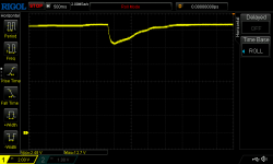
That does seem unusual- a 2V drop taking 1 second or more to recover (only as the note dies down). With headphones there is very little loading on the output amp compared to the speaker, so I would not expect a droop this big. Was this also seen on the -13 rail?
The rectifier could have a bad diode (Did the output amp previously short?) If there were a bad diode, the bridge rectifier becomes a half wave rectifier for one side, so one side would have twice as much ripple as the other side (and the ripple would be at 60Hz instead of 120Hz) but that would not explain the lower output signal- a bad cap would however. If you listened to the op-amp outputs and they seemed normal, it seems the problem would be with the output, and if it is working properly again, points to the bypassing. Yep, I'd do all of the caps in the power supply and go from there.
The rectifier could have a bad diode (Did the output amp previously short?) If there were a bad diode, the bridge rectifier becomes a half wave rectifier for one side, so one side would have twice as much ripple as the other side (and the ripple would be at 60Hz instead of 120Hz) but that would not explain the lower output signal- a bad cap would however. If you listened to the op-amp outputs and they seemed normal, it seems the problem would be with the output, and if it is working properly again, points to the bypassing. Yep, I'd do all of the caps in the power supply and go from there.
Yes, the droop is mirrored on the negative side of the 13V rail and perfectly correlates with the volume of the note. Interestingly, this only happens on the drive channel. On clean, there is no droop (but also not really any sound).
But in any case, I think I can't debug any further without replacing the caps (and I'm becoming increasingly suspicious of the first two op-amps). I'll have to order in some parts.
But in any case, I think I can't debug any further without replacing the caps (and I'm becoming increasingly suspicious of the first two op-amps). I'll have to order in some parts.
Change the PSU main caps, and if possible, change the rectifiers / bridge.
And the noise can come from poor shield or earthing, melt all the solder joints connecting to sheild, and also spray the jacks, bad connection at spring can also be an issue.
And check the line in to earthing capacitors.
If the capacitors are not from a reputed brand, or they are more than 15 years old, change them as a matter of course.
I changed a 'good' looking capacitor on my printer, it was restarting at random, Samhwa 470 uF/25 V...put a Keltron (Sprague licence, very good) 35V instead, what I had in stock. Problem solved.
I think poor connection, induced noise, overgain and supply sag are the issues to be checked before checking the low voltage (signal input) side.
I prefer Keltron, rather than fake Japanese or Chinese, and sometimes Keltron fakes are sold here!
Except as a user, no ties to any names above.
Well, the good news is that after replacing all the electrolytic caps, the bridge rectifier, the op-amps and the power amp, the problem is solved.
The bad news is that I'm not sure which one of these it was! The reason being that after replacing each component, I tested the amp via the phones jack using a iPhone-style headset (via 3.5mm to 1/4" adapter), and not the speaker. As I later learnt, the amp always sounds wrong via this method, since the iPhone jack is not the usual TRS-type jack; and so thus I kept thinking something was awry and went on replacing the usual suspects. Lesson learnt, I suppose!
Amps sounds great now, and it's nice to know that there are now some quality components inside (I went for the NE5532, and better-spec caps all round).
Thanks for the guidance, all.

While a forensic autopsy would have told which organ failed, it's academic, and only serves as emotional closure. You fixed it, it did not seem to break the bank, and now you have good reason to celebrate. Sounds like it will serve well for years to come. Good job, and well done. Glad you hung in there.
- Home
- Amplifiers
- Solid State
- Repairing 'farty' Vox Pathfinder 10