Good day all,
I would appreciate some help to troubleshoot the fault the amp above has.
I bought this amp a year ago and last month 2 caps blew up. After this i did a full recap
So far so good, amp was working fine but I wanted to adjust the idle current closer to the needed 20mV, it was still a bit on the high side. I was in a hurry and I layed down the amp the wrong way around and put the probes on the wrong legs of the Transistor; Instead of the two left legs I have put them on the right legs one 1 channel.

A nice "poof" occured and after measuring the desoldered transistors, the TR7b as above was toast.
I replaced all 4 output transistor and while i needed to order parts anyways I also changed the 612K transistor, as can be found in the attached schematic.
After powerup the 2 4A fuses still blow right away. I checked the TR5 and TR6 and they measure fine.
I eyaballed all components on the PCB and nothing looks burned.
All wires are soldered with pins with wire twisted around them so it is not quite convinient to troubleshoot via disconnecting sections.
I hope someone could push me in the right direction what to check next?
Thank you al in advance!
I would appreciate some help to troubleshoot the fault the amp above has.
I bought this amp a year ago and last month 2 caps blew up. After this i did a full recap
So far so good, amp was working fine but I wanted to adjust the idle current closer to the needed 20mV, it was still a bit on the high side. I was in a hurry and I layed down the amp the wrong way around and put the probes on the wrong legs of the Transistor; Instead of the two left legs I have put them on the right legs one 1 channel.
A nice "poof" occured and after measuring the desoldered transistors, the TR7b as above was toast.
I replaced all 4 output transistor and while i needed to order parts anyways I also changed the 612K transistor, as can be found in the attached schematic.
After powerup the 2 4A fuses still blow right away. I checked the TR5 and TR6 and they measure fine.
I eyaballed all components on the PCB and nothing looks burned.
All wires are soldered with pins with wire twisted around them so it is not quite convinient to troubleshoot via disconnecting sections.
I hope someone could push me in the right direction what to check next?
Thank you al in advance!
Attachments
Putting your voltmeter across the wrong legs would not cause the magic smoke to escape. What could, however, would be shorting the terminals of the transistors.
The 20mV you're referring to sounds like it should be measured across the emitter resistors, not the output transistors Vbe.
I had a look at the schematic and it seems to imply the darlington arrangement output transistors have a 0.47K resistor as emitter resistor on the high gain end of the darlington pair. That doesn't sound right. Can you confirm these are, rather, 0.47 OHMS? That would make the 150 ohms resistors to the emitters of the low gain end make sense.
You can choose to adjust bias current in a few different ways if you do not have conclusive answers as to where to measure. You can gauge for a transistor base to emitter number, measure across the emitter resistors if that value is known or could be calculated, or just wing it with "a little more than where crossover distortion is gone"
Thanks for you answer!
I think you are correct about the bias meaurement. The service manual I have is of very poor quality and if I look closely now on PC screen indeed it should have been measured on the resistors. On the printout it looks it needs to be measured on the trannies directly.
The resistors are indeed 0,47K ones as per the writing on them. But I just found out all 4 measure (on boths channels) 1,3Ohms. (tested in desoldered condition) Can they degrade over time?
Today I measured more components and the 2SA965 and the C2235 are toast, the 150 ohms resistors are overheated (black) but still measure 150 Ohms.
Also the 2SC1815 is gone.
I will replace the 2SA965 and C2235 with TTA004B and TTC004B since originals are only available from aliexpress or Ebay. 2SC1815 and ofcourse the resistors are still available.
Will check the diodes in the circuit tomorrow to see if they are stil OK.
They can degrade, but they rarely if ever go short circuit. There's pretty much no way for them to go short; they're a piece of wire in most cases here. Remove them from the board on at least one side (one of two legs) and measure again. Oops, missed that you already did.
Let's first make sure "0.47K" is actually meant to be 470 ohm. That would be really surprising to me, for the large current transistor out of the two.
Edit: the "0.47 (K)" looks distinct from the way the other resistors are marked "2.7k" or "15k". So I think the (K) is a denominator of some kind of variant, just like the FS likely means FuSible.
In any case, they should measure 0.47 ohms then. Check your meter leads. What is their short circuit resistance? Does it add up?
Yes I have completely desoldered them prior to measurement, thats what I do with all components that I measure.
My apologies, I edited my previous message. Please check the edited bits. 🤡
In what way did TR15 (type C1815) fail? Short between C-E?
In what way did TR5/TR6 (type C2235 / A965) fail? Shorted anywhere?
The C2235/A965 aren't super rare or special parts; you can replace them for troubleshooting purposes with rough equivalents that have the same or higher spec for voltage tolerance and the same footprint if you have any, and replace them with more specific parts later. 't is also cheaper if you blow things up again.
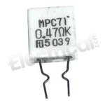

Looks like the K stands for Kinked leads. For dissipation and component health purposes, so it makes sense for the circuit schematic to also specify they need to be kinked/stood-off.
Yes indeed, tested on voltage and shorts with multimeter.My apologies, I edited my previous message. Please check the edited bits. 🤡
In what way did TR15 (type C1815) fail? Short between C-E?
In what way did TR5/TR6 (type C2235 / A965) fail? Shorted anywhere?
The C2235/A965 aren't super rare or special parts; you can replace them for troubleshooting purposes with rough equivalents that have the same or higher spec for voltage tolerance and the same footprint if you have any, and replace them with more specific parts later. 't is also cheaper if you blow things up again.
Unfortunately I have no similar transistor laying around so I just order the equivalents right away.
Looks like the K stands for Kinked leads. For dissipation and component health purposes, so it makes sense for the circuit schematic to also specify they need to be kinked/stood-off.
The K may indicate 10% tolerance. See chart below.
| Capacitor Code | Capacitor Tolerance |
| B | ± 0.1% |
| C | ± 0.25% |
| D | ± 0.5% |
| F | ± 1% |
| G | ± 2% |
| J | ± 5% |
| K | ± 10% |
| M | ± 20% |
Please use a DBT (dim bulb tester) to save blowing fuses and also potentially to save components from destruction under fault conditions. I would also link out TR15 (apply a shorting link) from collector to emitter to force zero bias. The amp will run normally like this as long as there are no other faults.
(so you don't need those transistors to continue 🙂)
Work on one channel at a time. Make sure all the low value resistors in each channel are OK (R13 to R18)
Don't buy transistors off eBay as there are many fakes around. I would think modern generic replacements would be fine on an an amp like this if original parts are hard to come by.
- Home
- Amplifiers
- Solid State
- Repair Akai AM2450