After doing a little tune-up on my recently aquired Akai M-7 tube amps (from the Akai reel to reel deck) I am pretty happy with the sound. I love the EL34 tube sound - smooth, seems to have plenty of bass (more than enough), good soundstage, etc.
I have been thinking about removing the tone controls, but have no idea how to go about it. Can I just remove them all together, or do I need to replace the pot with some type of 'bypass' curcuit, or do I need to add some type of jumper?
I have seen a few articles on removing tone controls from the PAS 2/3x, but nothing really generic...
BTW, the tone controls on all amps (I have 6 monoblocks), are fairly 'scrathy' anyway, and I really don't feel like they are needed in the first place....atleast for my application.
Thanks,
Wayne Boyd
Tone controls are generally configured as feedback networks. If you remove them, you'll need to replace them with flat feedback to keep the gain reasonable and distortion low.
In some cases, a tone control stage can be bypassed completely. You'll need to study the schematic, determine the gain structure, then figure out if that stage can be clipped out.
In some cases, a tone control stage can be bypassed completely. You'll need to study the schematic, determine the gain structure, then figure out if that stage can be clipped out.
if you measured the tone controll resistance when its in the position you like you could just replace it with a resistor of that value. Not the best solution but it should work.
you can take out the tone controls and if its a passive config replace with a volume pot or trim pot if the gain is too high
As Sy pointed out, if the tone control is in the feedback loop things can get a little sticky, BUT, if it's a passive circuit its a snap.
Look about halfway down this post and you will see the tone circuit of my Fisher 800C. I simply shunted the pins numbered 4 & 7 together, and voila', tone is bypassed, and I got around 6dB of extra gain.
Casey
Look about halfway down this post and you will see the tone circuit of my Fisher 800C. I simply shunted the pins numbered 4 & 7 together, and voila', tone is bypassed, and I got around 6dB of extra gain.
Casey
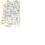
Ok, here is a partial of the schematic. The tone control is noted as VR2. It seems to be part of the preamp curcuit. I have not discovered, nor can I tell if it is passive or not. If someone wanted to take a look at the whole schematic, that would be great...I did not want to upload the whole thing and take up to much space.
Thanks,
Wayne Boyd
Thanks,
Wayne Boyd
Attachments
Looks like your in luck 😀
The 50p C5 in parallel with the 100k R8 tilts the highs up, this feeds the junction of C5-C6. C5 and Vr2 is a low pass that tilts the highs down to flat when Vr2 is in its mid position, further cutting the highs as it gets lower in resistance, and "boosts" the highs as its increased...tone control.
Remove the 50p (C4) and the the .01uF (C5). This will kill the tone control, and raise the gain. If the gain is to high, put a resistor from ground to the C6-R8 junction, making a voltage divider. If it were me, I would connect C6 directly to the grid of V2a, bypassing the play/record switch..a notorious point of failure.
If Iv'e made a boo-boo in my analysis I hope one of the more learned people on this forum will correct me.
Casey
That was exactly my take, FWIW. Play/record switches are useful for approximately 0.001% of modern audiophiles.
- Status
- Not open for further replies.
- Home
- Amplifiers
- Tubes / Valves
- Removing tone controls - Need a little help