Ah, but they are.
In general, the frequency response magnitude at a point on the unit circle is equal to the product of the lengths of the vectors from all of the zeroes to that point, divided by the product of the lengths of the vectors from all of the poles to that point. In the case of an FIR filter, the distance from all of the poles is 1.
Similarly, the phase response at a point on the unit circle is equal to the sum of the angles from all of the zeroes to that point, minus the sum of the angles from all of the poles to that point. In the case of an FIR filter all of the pole angles are equal.
https://www.dsprelated.com/freebooks/filters/Pole_Zero_Analysis_I.html
Holy cr*p I did not know that... 😗 Now that I think about it, it does make perfect sense. I had always thought that the pole-zero concept didn't really apply to FIR filters. Obviously the depth of my signal processing knowledge could be... um... improved! 😛
Sorry for throwing my ignorance around, all. At least I learned something.
I suppose you mean global EQ? Was that really the summed understanding of the long thread which was based on my question wrt if one could more or less just do a rudimentary e.g. 1st order filter LP and a 2nd order HP to protect the 2 drivers and then in DSP see to that this system has a "perfect" magnitude and time behaviour. As such, the HP/LP filter used has compliantly "disappeared" in the system characteristics and can't be seen any more. (within reason - if one really tries to mess up that filter in the worst way possible, it will be har to recover... but why do that...)Guys, sorry, but I'll keep saying it till the cows come home.....
Global filtering is simply not a good idea, either IIR or FIR, for setting up multi-way loudspeakers.
- Will the filters still impose a trace on the directivity of the speaker? Probably yes!?
- If the compensated speaker has a "flat" GD behaviour - the filter would be "hidden"? It should be as its flat!?
- If the compensated speaker has a "flat" FR behaviour - the filter would be "hidden"? It should be as its flat!?
So if it's not a good idea it is directivity that is the culprit? Was that thread "summed up" in a common accepted understanding?
//
Guys, sorry, but I'll keep saying it till the cows come home.....
Global filtering is simply not a good idea, either IIR or FIR, for setting up multi-way loudspeakers.
There is a subtlety here that may be missing from the discussion. Consider the hypothetical case of a 2 way speaker with perfect LR4 minimum phase crossover. Also consider that the speaker exhibits the additional nonlinear phase and GD associated with the woofer cut off and tweeter high frequency roll off. The crossover can be passive, active analog, or active digital, FIR or IIR. Makes no difference. Assume that the speaker is bi-amped. We wish to make the speaker linear phase. There are two options, global correction of the system phase, or correction of the individual woofer and tweeter response to be linear phase. So what is the difference? If we choose global correction a single filter is developed that will correct for the nonlinear GD associated with all sources; the woofer cut off, the crossover, and the tweeter roll off. The input signal is passed through this filter then to each channel of the speaker. If we choose individual correction filter for the woofer and tweeter the woofer correction will consider only the woofer cut off and crossover induced GD while the tweeter correction will consider only the crossover and tweeter roll off induced GD. That is, the correction filters will be different. But note, nothing, not one iota about the actual speaker has changed. Not the frequency response, the phase response, the GD, the polar response, nothing. But if in either case you pass an impulse through the correction filter(s) and then the speaker, the impulse will be reproduced perfectly (in theory). The reason is not because the speaker is linear phase. The reason is because the correction filter(s) manipulate (distort) the phase relationships between the frequency components of the input impulse in such a manor that when passed through the speaker the original phase relationships of the input signal is restored. The correction filter(s) take out phase rotation and the speaker puts it back in.
Looking at this mathematically,
For global correction let the correction filter PL(w). Then,
PL(w) * (HP(w) + LP(w)) = PL(w) * HP(w) + PL(w) * LP(w)
The summed response on the left will mimic a linear phase system but the individual responses on the right will not. The net woofer response will have nonlinear phase at high frequency (in it's stop band) where as the net tweeter will have nonlinear phase at low frequency (in it's stop band).
For individual corrections, let PLl(w) be the woofer correction and PLh(w) be that of the tweeter.
Then,
PLl(w)*LP(w) + PLh(w)*HP(w) will mimic a linear phase system and each individual response will also mimic linear phase .
Both global and individual correction schemes yield the same result but in the global case the "distortion" of the input signal is identical for the woofer and tweeter sections where as in the individual case the signals sent to the woofer and tweeter are actually different. From my perspective, and the old adage KISS, I can not see how individual correction would be superior to global correction. In fact, if the speaker were to use and odd order Butterworth crossover the global option is the only alternative.
I agree with your mathematical assessment. But my agreement or disagreement with KISS, in this case, "depends".From my perspective, and the old adage KISS, I can not see how individual correction would be superior to global correction.
To me, it seems like optimizing two, e.g., 4th-order systems (crossover being one, loudspeaker driver being the other) is probably easier than optimizing one 8th-order system, simply because of the reduced degrees of freedom. Furthermore, once the procedure for optimizing a crossover has been established, that can be applied to any crossover, anywhere. It becomes (more or less) a set of fixed parameters, very accurately represented in the DSP math. Each loudspeaker driver, on the other hand, must be optimized separately, every time its circumstances change. Again, do you want to optimize a 4th-order system, or an 8th-order system?
So I don't think that we disagree on the fundamentals of the problem, just on how to solve it. I'm OK with that. It leaves room for creativity.
i didn't mean global EQ. I meant how we go about achieving flat mag and phase on a multi-way.I suppose you mean global EQ?
And from the perspective of a speaker builder/manufacturer, that is trying to make the best tuned speaker they know how. (anechoically/or quasi)
Good example to use, to help me explain my take on why global is not optimal.Consider the hypothetical case of a 2 way speaker with perfect LR4 minimum phase crossover. Also consider that the speaker exhibits the additional nonlinear phase and GD associated with the woofer cut off and tweeter high frequency roll off. The crossover can be passive, active analog, or active digital, FIR or IIR. Makes no difference. Assume that the speaker is bi-amped. We wish to make the speaker linear phase. There are two options, global correction of the system phase, or correction of the individual woofer and tweeter response to be linear phase. So what is the difference?
Fully agree, no difference....IF we are talking about 1D electrical space.If we choose global correction a single filter is developed that will correct for the nonlinear GD associated with all sources; the woofer cut off, the crossover, and the tweeter roll off. The input signal is passed through this filter then to each channel of the speaker. If we choose individual correction filter for the woofer and tweeter the woofer correction will consider only the woofer cut off and crossover induced GD while the tweeter correction will consider only the crossover and tweeter roll off induced GD. That is, the correction filters will be different. But note, nothing, not one iota about the actual speaker has changed. Not the frequency response, the phase response, the GD, the polar response, nothing.
When we use global correction, I know a FIR filter must be long enough to correct the lowest frequency of interest.
And the higher frequencies get corrected within that longer filter.
I've found looking at the impulse response of global filters, that the one filter usually has lot of impulse fuzz.
Fuzz that stretches out in time on both sides of the impulse peak, (due to length of filter.)
Whereas with individual corrections, a long filter can used for the lowest driver, with progressively shorter filters used for higher frequency sections.
Frequency dependent FIR filter length if you will.
I think decreasing FIR filter length with frequency helps minimize the time window width of potential misapplied corrections or pre-ring as frequencies rise.
I've learned to try to get each sections linear phase impulse response, as clean as possible, trading that against as short as possible.
(Using fixed delays between unequal filter length sections.)
The key for me has been to look at the electrical filter's impulse, .....and not just stopping at acoustic transfer & impulse, think acoustic response says it all.
Because...I think electrical impulse fuzz is noise....that we hear though our speakers all the time.
With otherwise identically near perfect acoustic transfer and impulse response on my multi-ways. ....
.....when each section's electrical impulse is comparatively cleaner & again shorter, its like the entire speaker's noise floor is lowered.
Subtle, yet obvious.
Speaker at low volume sounds particularly better. Dynamics sound improved without SPL metering any higher. Loud sounds even more alive.
And I've yet to see a global FIR file, covering low to high, have the filters electrical impulse look really good.
Some two-ways have been OK, when starting with an already excellent speaker....and leaving the woofer cut off alone. Past that, not so good..
Agree with that, each person has different loudspeakers and different SPL / phase / group delay characteristics that they need to address themselves.Furthermore, once the procedure for optimizing a crossover has been established, that can be applied to any crossover, anywhere. It becomes (more or less) a set of fixed parameters, very accurately represented in the DSP math. Each loudspeaker driver, on the other hand, must be optimized separately, every time its circumstances change.
However, crossovers are fairly standard (BUT, LR etc.) and all their parameters may even be shared over an internet forum and someone else on the other side of the globe could still make use of it, even if their crossover frequency were different.
Now, my loudspeaker's SPL / phase and GD are almost useless to my next door neighbour, unless he is planning on buying it from me. 😉
I think, perhaps, you didn't get my point entirely. Suppose you have a speaker that isn't linear phase to start with.. That seems to be the objective of the original post. It can be any speaker, and you want to correct it to behave as a linear phase system. You can measure the response, say it's SP(w). Now it is desired to generate a correction filter so that the response is SPLP(w), where the phase of SPLP(w) = w*Td. That is, same amplitude response but linear phase. You have
SPLP(w) = PL(w) * SP(w), or
PL(w) = SPLP(w) / SP(w).
PL(w) is an all pass filter with phase equal to the negative phase of SP(w) plus the delay associated with SPLP(w). Process the input through this filter (FIR) and feed it to the speaker. It can be single amp or multi amp, any type of crossover.... The speaker's output will mimic a linear phase system.
Consider a speaker with a B3 acoustic crossover. How would you develop separate correction filters for the woofer and tweeter?
With regard to "buzz" that's a matter of numerical accuracy. I suspect a hardware issue and it may be true that it could be an issue. No argument there.
Last edited:
I think I fully understood.
I think what's missing, is what we actually have to do to build filters. How we have to make acoustic measurements and work from them.
And how the imperfections in 3D real world space, don't tie together so elegantly as the do in 1D mathematical space.
Correcting drivers cutoff or rolloffs, is never as clean in practice ime, as in sims. Trying to accommodate for the measured realities in one filter is simply suboptimal, again ime.
A B3 acoustic crossover? Well I wouldn't use it, i'd use a fully complementary crossover. I'd probably make the acoustic targets linear phase LR4s.
Easy FIR to build.
The fuzz, not buzz 🙂, is the filter trying to correct in time, what it shouldn't be...
I have to run now. Will post an example when back
I'm not certain what you're asking, here. In my comment above, I was referring specifically to "exotic" crossovers (such as symmetric FIR filters, or any filter that cannot be described by a standard ARMA transfer function, i.e., nontrivial numerator and denominator). In such cases I believe that it's generally easier to optimize the crossover and the driver separately. However, if the desired crossover transfer function is ARMA, and the loudspeaker response can also be characterized in the same way, then it's often appropriate and advantageous to incorporate the existing loudspeaker transfer function into the desired crossover transfer function. As an example of this, the Linkwitz Transform is not limited to extending the low-frequency response of a woofer; it can just as easily transform the existing woofer highpass transfer function into the desired crossover highpass transfer function (or a portion of it, if the crossover filter order is greater than the woofer filter order). As this latter case can perhaps be called an example of "global" optimization, you can see that I'm not against it in all cases.Consider a speaker with a B3 acoustic crossover.
Last edited:
Take a 2 way loudspeaker, with tweeter above the woofer. Suppose the complete speaker System including analog and digital filtering . . .
has a perfect group delay.
Now, adjust your ear height to the center of the woofer.
Now, adjust your ear height to the center of the tweeter.
Now, adjust your ear height to the middle of the centers of the woofer and tweeter.
Those 3 conditions can not all have perfect group delay;
And those 3 conditions can not all have perfect frequency response, comb filtering prevents that.
Only one ear height can be correct for group delay; and correct for frequency response.
Any solution is only true if the complete system is designed properly.
In this case, the system has to be adjusted for at least the drivers, their relative vertical spacing, and the ear height, or the system is not perfect.
Before I forget, the distance from the drivers to the listeners ear is another part of the system.
Are we peeling the outer layers off the Onion, or the meaty layers of the Onion, or the core of the Onion?
Some excellent engineers are not necessarily also excellent system engineers.
$0.04
Inflation has taken over again
But each driver can have perfect group delay within its passband.Those 3 conditions can not all have perfect group delay
Only true at and near the crossover frequency.And those 3 conditions can not all have perfect frequency response, comb filtering prevents that.
The inability achieve perfection at all frequencies and all polar angles is not a reason to ignore the responses of the crossovers and drivers. One makes whatever improvements one can. Often the hardest part is deciding what to improve.Any solution is only true if the complete system is designed properly.
gberchin,
Often, the hardest part is to decide what is Paramount:
Make it generally best for a wide variety of listeners systems
Make it best for an exact speaker system (system of drivers, hardware crossover, digital filter, speaker L & R distance, listener distance, etc.)
Make it best for true stereo recordings of symphonies, that have an almost circular XY Bloom . . .
Or make it best for those stereo recordings that put almost everything in the center, the XY looks like a fat 45 degrees upward sloping line.
Etc.
Sound reproduction is an art and a science.
Place the listener in the concert hall.
Place the Jazz trio into the listener's room.
Hard to do, but a worthwhile goal.
Entertainment using sound reproduction is often an art plus the knowledge of what fools the listener into thinking the sound is good.
Entertainment in a Movie is different than just listening to a stereo recording only for the sound, instead of the total of visual and sound.
Just my $0.03
adjusted for inflation
gberchin,
Comb filtering only in the crossover region?
Like a typical 2 way speaker, crossing over at a frequency where the ears are the most sensitive?
I heard with both ears for many decades.
Then I heard with only one ear for over a decade.
I learned so much about stereo sound, especially from the change of two ears, to one ear.
I started using XY plots to understand some of the things I was hearing.
I still have a lot of investigation to know more about it.
Never stop learning
Perhaps. But as you pointed-out, what is paramount is not always something that can be improved.Often, the hardest part is to decide what is Paramount
gberchin,
Define what the system consists of, and how the complete system will be used.
System: single instrument or group, recording studio or concert hall, microphones and placement, mic preamp and everything all the way through the final production house's adjustments, Then the home CD or Vinyl signal source, pre and power amplifiers, loudspeakers, listener position, and room.
A System has many links. Some can be manipulated or compensated for, right at that link, some can be corrected later on, and some can not be corrected at all; the link is essentially bad or even worse is broken.
No system definition, no target. No target, no bulls eye. No winner in that scenario.
When a Stereo equipment setup does not have a good stereo sweet spot, it might not be the equipment or the room, it might be the recordings.
Must be a problem with how the filters you've examined were designed. The global phase correction filters I generate have no such problem. Here's an example 3-way crossover (LR4@85Hz, LR6@1050Hz), first uncorrected:I've found looking at the impulse response of global filters, that the one filter usually has lot of impulse fuzz.
Fuzz that stretches out in time on both sides of the impulse peak, (due to length of filter.)
[...]
I've yet to see a global FIR file, covering low to high, have the filters electrical impulse look really good.
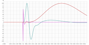
Electrical sum of the above:
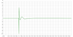
Now with the global phase correction filter applied (2048 taps):
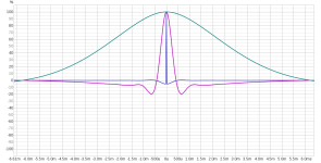
Electrical sum:
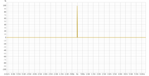
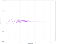
Correction filter magnitude response (note the vertical scale):
I think, perhaps, you didn't get my point entirely. Suppose you have a speaker that isn't linear phase to start with.. That seems to be the objective of the original post. It can be any speaker, and you want to correct it to behave as a linear phase system. You can measure the response, say it's SP(w). Now it is desired to generate a correction filter so that the response is SPLP(w), where the phase of SPLP(w) = w*Td. That is, same amplitude response but linear phase. You have
SPLP(w) = PL(w) * SP(w), or
PL(w) = SPLP(w) / SP(w).
PL(w) is an all pass filter with phase equal to the negative phase of SP(w) plus the delay associated with SPLP(w). Process the input through this filter (FIR) and feed it to the speaker. It can be single amp or multi amp, any type of crossover.... The speaker's output will mimic a linear phase system.
Consider a speaker with a B3 acoustic crossover. How would you develop separate correction filters for the woofer and tweeter?
With regard to "buzz" that's a matter of numerical accuracy. I suspect a hardware issue and it may be true that it could be an issue. No argument there.
Let's go back to this. Given that you now have PL(w) yuo can apply it as.
Since the same PL filter is applied to both the HP and LP sections the inter-driver phase difference between HP and LP section will remain the same and the summed response will remain and the speaker will perform as if it is a linear phase design.
By contrast, if you different PL filters for the HP section, say PLh and low pass section of the speaker, say, PLl and apply them as
then there is the potential to alter the inter-driver phase difference and the result, while it may be linear phase, may not sum as it did originally (i.e. the B3 case).
In the LR4 case it doesn't make a difference because the inter-driver phase difference through the x-o region is zero and if you make the LP and HP responses linear phase with the same GD they will still sum properly. But that is not the case where the inter-driver phase difference is not zero. The bottom line is that the correction all pass filter should be based on linearizing the system response.
OK ... I think I understand your point, now. It has always been my assumption that what you stated above is exactly the case. That is to say, it doesn't make any sense to linearize the woofer response to constant delay of "x", and to linearize the tweeter response to constant delay of "y", y != x, regardless of whether the linearization is done in the crossover or globally. Similarly, in an "n-way" crossover, the final delay in all of the passbands has to be equal, regardless of the individual delays associated with each crossover pair. The multiway crossover depicted in my MDS Tutorial does this automatically, but if a different configuration is used, then the delay equalization has to be performed explicitly.The bottom line is that the correction all pass filter should be based on linearizing the system response.
I remember listing to the sloped front panel of Spica TC-50 speakers. A very good LCR crossover. Real Good group delay at middle frequencies.
Fortunately, I heard the Spicas driven by 2 stage single ended amplifiers with WE 212E tubes, with Thoriated Tungsten filaments, lighting up the ceiling.
The Spica speaker can still be purchased used.
The WE 212E amplifiers are much harder to purchase.
But Oh, what a glorious sounding stereo system!
Must be a problem with how the filters you've examined were designed. The global phase correction filters I generate have no such problem. Here's an example 3-way crossover (LR4@85Hz, LR6@1050Hz), first uncorrected:
View attachment 1378965
Electrical sum of the above:
View attachment 1378966
Now with the global phase correction filter applied (2048 taps):
View attachment 1378968
Electrical sum:
View attachment 1378969
Correction filter magnitude response (note the vertical scale):
View attachment 1378976
Guys, sure...in the electrical domain...global vs individual makes no difference. We can all agree, Ok?
But what about the 3D acoustical measurement domain?
Take your example above, the first panel showing 3 minimum-phase pass bands. And with all three pass bands having correct relative timing,... that is their initial impulse rises all starting at T=0.
What happens if they don't all start/rise at T=0 ?
Well, pure FIR global impulse inversion in the electrical domain will still correct them to linear phase pass bands...but only / narrowly for the specific time offsets from T=0 rising starts.
And how dang easy is is to nail down acoustic passbands' min-phase impulse starts? For establishing low frequency timing, it's difficult at best !!!
Real world global correction based on acoustic measurements, implicitly assumes relative measured timings are spot on, ....like electrical always are..
Error gets magnified away from given measurement spot and FFT determination.
All that's one time domain issue...a form of "tune to a spot" like global FIR room correction inevitably suffers.
The form I was addressing earlier, is when driver cut offs / rolloffs get summed together for corrections. Shorter filter lengths are needed for higher freq drivers than lower ones, to help keep passbands' individual gack, confined to their own passband.
- Home
- Loudspeakers
- Multi-Way
- Removing Loudspeaker Group Delay using reverse-IIR filtering