hi guys
i have a DAC which has an output capacitor that is 10uF. which then connected to a tube buffer that has the input cap of 0.33uF.
my question:
1. is this setup recommended? with 2 caps in series and separated by an interconnect?
2. can i remove one of the caps? which is better removed? output cap of the DAC or the input cap of the tube buffer?
3.i am planning to put this DAC and tube buffer in the same chassis. what is my better option?
thx in adv
regards Erwin

in engineering the safe answer is "it depends"
in this case V rating could be an issue with tube circuits operating at 10-100x the V that a typical DAC output cap may be blocking
likely the 10u DAC output cap will not have a high enough V rating for the tube circuit
so the safer approach would be to keep the tube amp input cap and possibly remove/short the DAC cap if you want to reduce the order of the low frequency roll off
Hi Jcx
i have check that the voltage required for the input of the tube buffer is less than 100v. its around 55v if im not mistaken.
while the output cap of the DAC is also rated 100v. actually 63v before the cap upgrade.
does this affect your proposed solution? thx
i have check that the voltage required for the input of the tube buffer is less than 100v. its around 55v if im not mistaken.
while the output cap of the DAC is also rated 100v. actually 63v before the cap upgrade.
does this affect your proposed solution? thx
if operating V works out then you could try eliminating either one of the caps
all else being equal the larger value cap would give a lower corner freuency which has several good effects
but some believe cap dielectric/construction makes audible differences - again more "it depends"
I believe that meaningful subjective lstening tests are really hard to do so I go with the best mainstream audio engineering recommendations - preferably choices that can be verified by measurement and comparison to published psychoacoustic thresholds
Hi Molly
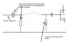
there is no resistor to the ground at the dac side.
there is a resistor after the capacitor after the capacitor at the tbe buffer side.
my tube buffer is in the link below:
http://www.diyaudio.com/forums/showthread.php?s=&threadid=96681
thanks
there is no resistor to the ground at the dac side.
there is a resistor after the capacitor after the capacitor at the tbe buffer side.
my tube buffer is in the link below:
http://www.diyaudio.com/forums/showthread.php?s=&threadid=96681
thanks
Hi Molly
there is no resistor to the ground at the dac side. i got no schematic of the dac. but i am sure that there is a output caps that are series with the output
there is a resistor after the capacitor after the capacitor at the tbe buffer side.
my tube buffer is in the link below:
http://www.diyaudio.com/forums/showthread.php?s=&threadid=96681
thanks
Hi,
If the buffer is exactly like in post #1 of the link I would go with jcx's suggestion of linking out the 10 mfd cap in the DAC.
When you have linked the cap measure if any DC voltage present at DAC output. If there is then as long as you ONLY use the DAC with that buffer there is no problem.
If the buffer is exactly like in post #1 of the link I would go with jcx's suggestion of linking out the 10 mfd cap in the DAC.
When you have linked the cap measure if any DC voltage present at DAC output. If there is then as long as you ONLY use the DAC with that buffer there is no problem.
the tube buffer circuit shows ~150 V supply - I would use that as the starting point for the blocking cap rating, not the nominal 55V operating point - if a Al electrolytic is used also check the bias point as the cap's leakage current could change it
it simply isn't safe to use a cap with a lower rating than the attached device's power pin V
with such high voltages you may want safety rated caps and to beef up the DAC output with some clamp diodes from the DAC out to the DAC PS&gnd that can carry the tube supply's max current until the fuse blows
I would recommend similar clamping on the output of the buffer as well
anyone working with amps, esp. tube circuits should be aware of shock hazards and any equipement that ever leaves your bench top should be designed and built to meet or exceed consumer electrical equipment safety standards
jcx said:the tube buffer circuit shows ~150 V supply - I would use that as the starting point for the blocking cap rating, not the nominal 55V operating point - if a Al electrolytic is used also check the bias point as the cap's leakage current could change it
it simply isn't safe to use a cap with a lower rating than the attached device's power pin V
with such high voltages you may want safety rated caps and to beef up the DAC output with some clamp diodes from the DAC out to the DAC PS&gnd that can carry the tube supply's max current until the fuse blows
I would recommend similar clamping on the output of the buffer as well
anyone working with amps, esp. tube circuits should be aware of shock hazards and any equipement that ever leaves your bench top should be designed and built to meet or exceed consumer electrical equipment safety standards
Hi Guys. Thx for the input.
Jcx, the tube buffer input caps are 400v rated polyester. good enough?
safety rated cap you meant is X2 rated caps?
i got no clue about "clamp diode", mind elaborate? thx
there are too many considerations to give detailed electrical safety directions in a forum thread
you need consider both shock hazard and fire hazard
the ususal shock safety scheme is to interpose conductive, safety grounded metal sufficient to conduct the worst case fault current in between people and the electronics
current limiting by fuses limits the max current and should also prevent failed components from overheating to the point of starting a fire
X rated caps are designed to fail safely when local internal shorts happen due to V spikes across the power line - they can't be relied on to "clear" when connected to higher impedance circuitry inside your amp
- Status
- Not open for further replies.
- Home
- Design & Build
- Parts
- removing input or output capacitor help